High-resolution timer (HRTIM) RM0440
874/2126 RM0440 Rev 4
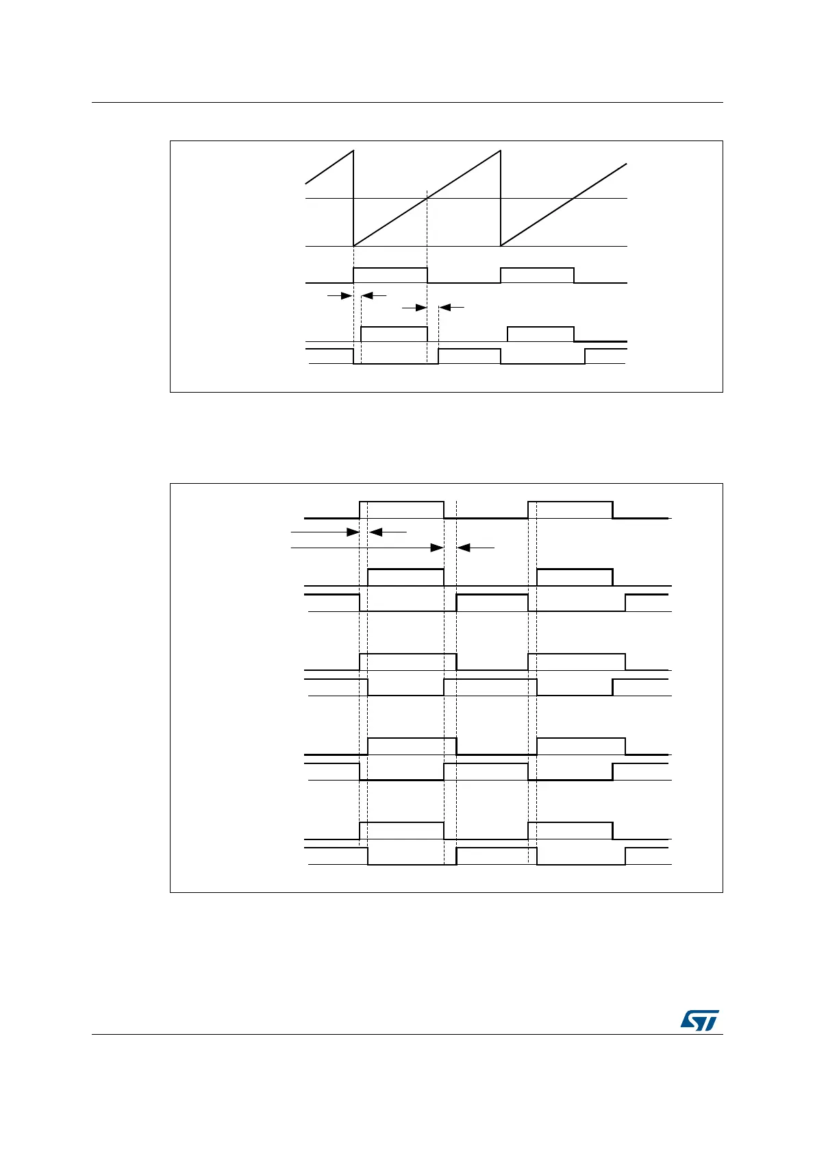
Figure 198. Complementary outputs with deadtime insertion
Negative deadtime values can be defined when some control overlap is required. This is
done using the deadtime sign bits (SDTFx and SDTRx bits in HRTIM_DTxR register).
Figure 199 shows complementary signal waveforms depending on respective signs.
Figure 199. Deadtime insertion versus deadtime sign (1 indicates negative deadtime)
The deadtime values are defined with DTFx[8:0] and DTRx[8:0] bitfields and based on a
specific clock prescaled according to DTPRSC[2:0] bits, as follows:
t
DTx
= +/- DTx[8:0] x t
DTG
where x is either R or F and t
DTG
= (2
(DTPRSC[2:0])
) x (t
HRTIM
/ 8).
MS32270V2
Deadtime rising
Counter
Compare
Deadtime falling
Crossbar output 1
HRTIM_CHx1
HRTIM_CHx2
MS32271V1
Deadtime rising
Deadtime falling
SDTRx = 0
SDTFx = 0
SDTRx = 1
SDTFx = 1
SDTRx = 0
SDTFx = 1
SDTRx = 1
SDTFx = 0
Out 1 (from crossbar)