RM0440 Rev 4 1299/2126
RM0440 General-purpose timers (TIM2/TIM3/TIM4/TIM5)
1343
1. Configure TIM_mstr master mode to send its Output Compare 1 Reference
(tim_oc1ref) signal as trigger output (MMS=100 in the TIM_mstr_CR2 register).
2. Configure the TIM_mstr tim_oc1ref waveform (TIM_mstr_CCMR1 register).
3. Configure TIM_slv to get the input trigger from TIM_mstr (TS=00010 in the
TIM_slv_SMCR register).
4. Configure TIM_slv in gated mode (SMS=101 in TIM_slv_SMCR register).
5. Enable TIM_slv by writing ‘1 in the CEN bit (TIM_slv_CR1 register).
6. Start TIM_mstr by writing ‘1 in the CEN bit (TIM_mstr_CR1 register).
Note: The slave timer counter clock is not synchronized with the master timer counter clock, this
mode only affects the TIM_slv counter enable signal.
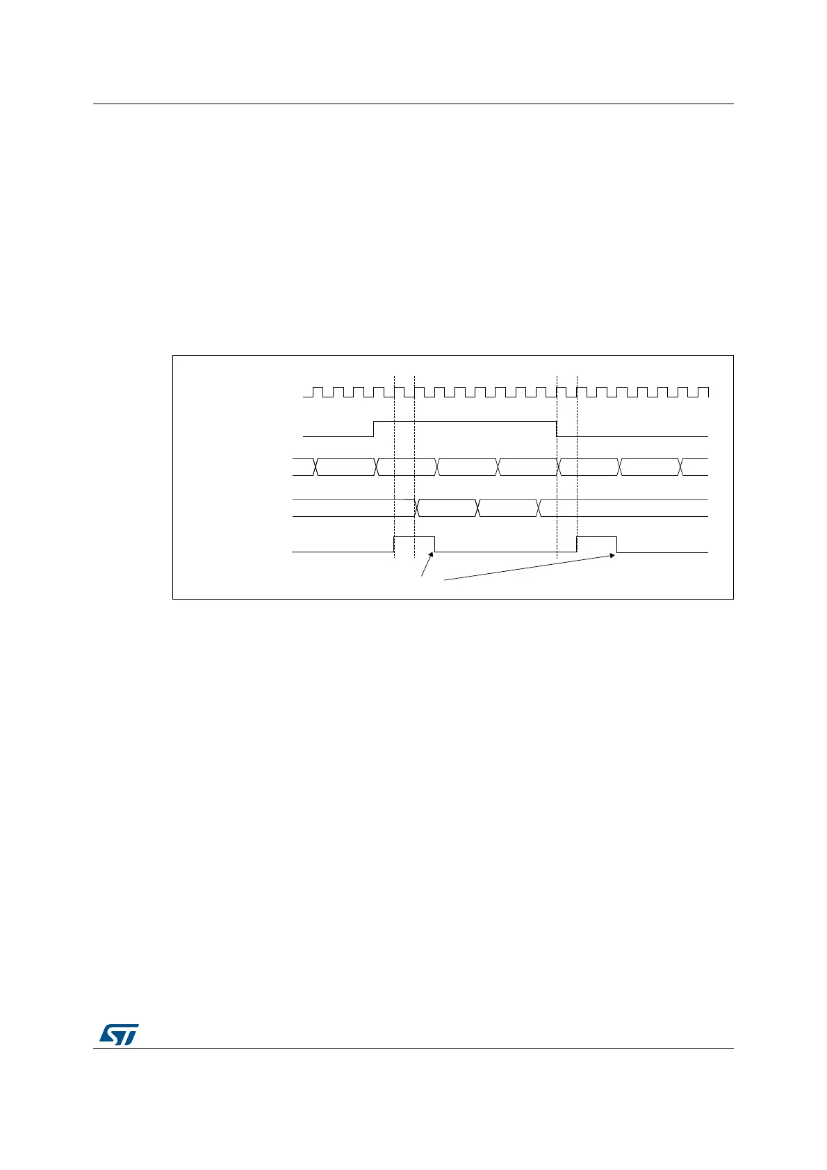
Figure 434. Gating TIM_slv with tim_oc1ref of TIM_mstr
In the example in Figure 434, the TIM_slv counter and prescaler are not initialized before
being started. So they start counting from their current value. It is possible to start from a
given value by resetting both timers before starting TIM_mstr. Then any value can be written
in the timer counters. The timers can easily be reset by software using the UG bit in the
TIMx_EGR registers.
In the next example (refer to Figure 435), we synchronize TIM_mstr and TIM_slv. TIM_mstr
is the master and starts from 0. TIM_slv is the slave and starts from 0xE7. The prescaler
ratio is the same for both timers. TIM_slv stops when TIM_mstr is disabled by writing ‘0 to
the CEN bit in the TIM_mstr_CR1 register:
MSv62376V1
tim_ker_ck
FC FD FE FF 00 01
TIM_mst_oc1ref
tim_mstr_CNT
30463045 3047 3048
tim_slv_CNT
tim_slv TIF bit
Write TIF = 0
 Loading...


