Serial peripheral interface / integrated interchip sound (SPI/I2S) RM0440
1780/2126 RM0440 Rev 4
39.9 SPI and I2S registers
The peripheral registers can be accessed by half-words (16-bit) or words (32-bit). SPI_DR
in addition can be accessed by 8-bit access.
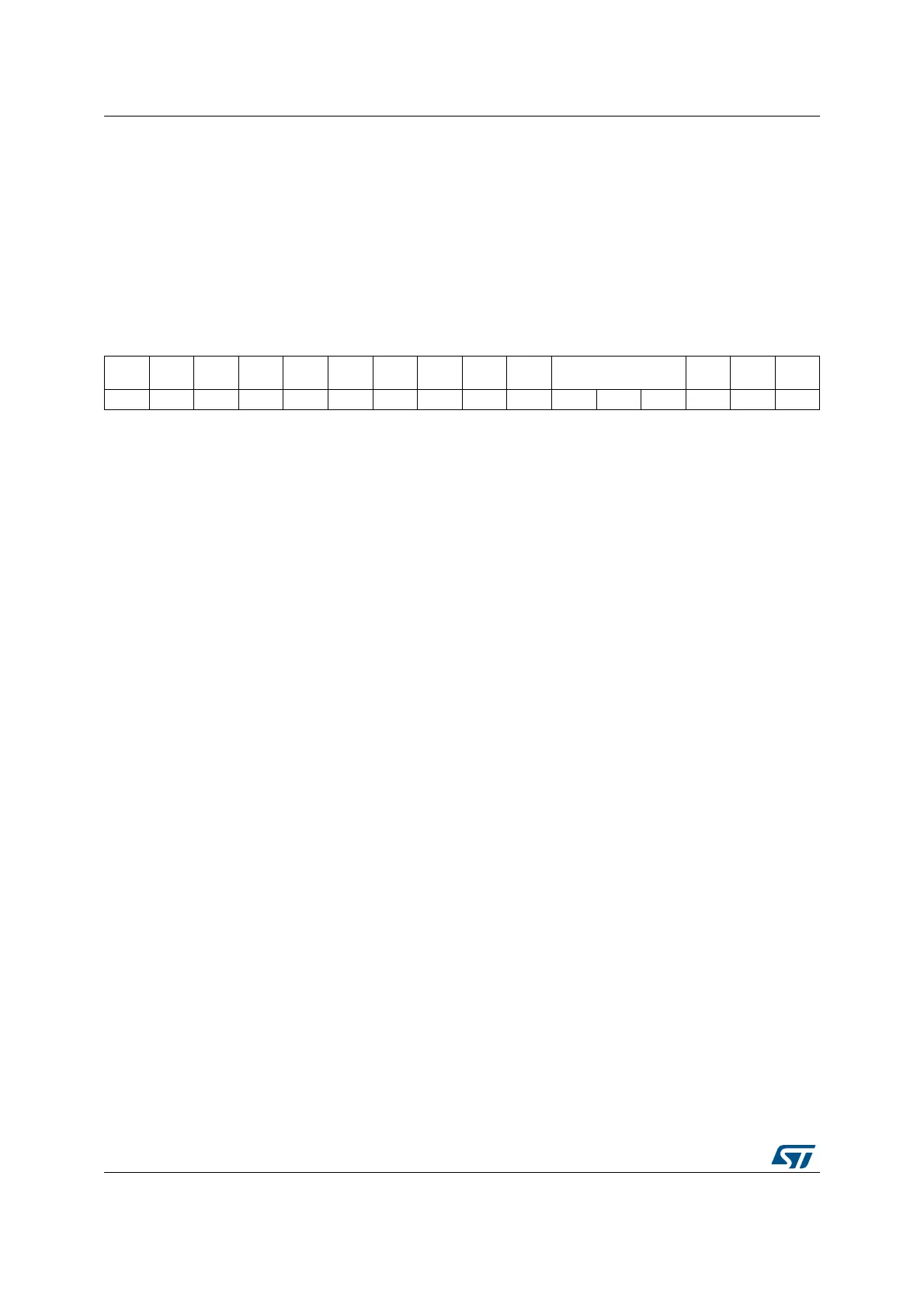
39.9.1 SPI control register 1 (SPIx_CR1)
Address offset: 0x00
Reset value: 0x0000
1514131211109876543210
BIDIM
ODE
BIDIOE
CRCE
N
CRCN
EXT
CRCL
RXONL
Y
SSM SSI
LSBFIR
ST
SPE BR[2:0] MSTR CPOL CPHA
rw rw rw rw rw rw rw rw rw rw rw rw rw rw rw rw
Bit 15 BIDIMODE: Bidirectional data mode enable.
This bit enables half-duplex communication using common single bidirectional data line.
Keep RXONLY bit clear when bidirectional mode is active.
0: 2-line unidirectional data mode selected
1: 1-line bidirectional data mode selected
Note: This bit is not used in I
2
S mode.
Bit 14 BIDIOE: Output enable in bidirectional mode
This bit combined with the BIDIMODE bit selects the direction of transfer in bidirectional
mode.
0: Output disabled (receive-only mode)
1: Output enabled (transmit-only mode)
Note: In master mode, the MOSI pin is used and in slave mode, the MISO pin is used.
This bit is not used in I
2
S mode.
Bit 13 CRCEN: Hardware CRC calculation enable
0: CRC calculation disabled
1: CRC calculation enabled
Note: This bit should be written only when SPI is disabled (SPE = ‘0’) for correct operation.
This bit is not used in I
2
S mode.
Bit 12 CRCNEXT: Transmit CRC next
0: Next transmit value is from Tx buffer.
1: Next transmit value is from Tx CRC register.
Note: This bit has to be written as soon as the last data is written in the SPIx_DR register.
This bit is not used in I
2
S mode.
Bit 11 CRCL: CRC length
This bit is set and cleared by software to select the CRC length.
0: 8-bit CRC length
1: 16-bit CRC length
Note: This bit should be written only when SPI is disabled (SPE = ‘0’) for correct operation.
This bit is not used in I
2
S mode.
 Loading...


