RM0440 Rev 4 1977/2126
RM0440 FD controller area network (FDCAN)
2008
RAM until the counter has counted down to 0, the counter stops and interrupt flag IR[WDI]
bit is set. The RAM Watchdog Counter is clocked by the fdcan_pclk clock.
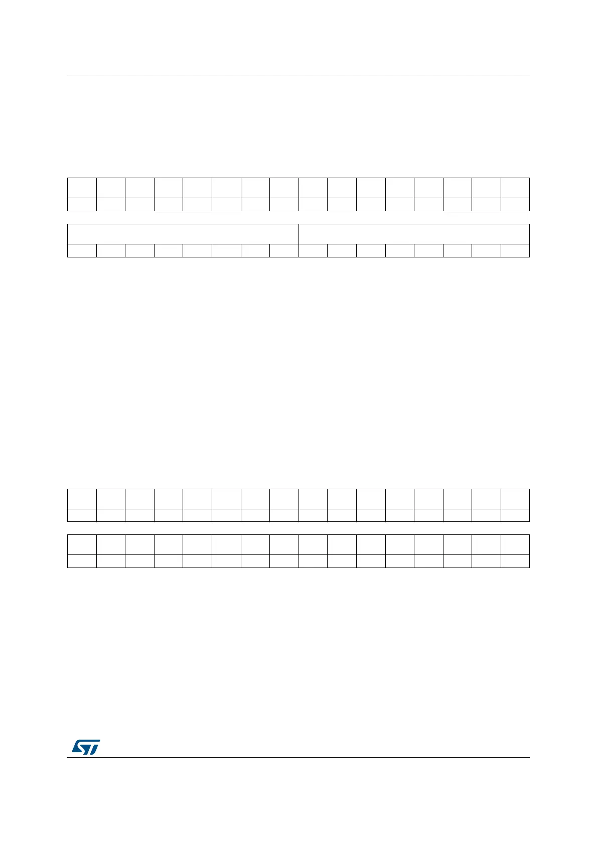
Address offset: 0x0014
Reset value: 0x0000 0000
44.4.6 FDCAN CC control register (FDCAN_CCCR)
Address offset: 0x0018
Reset value: 0x0000 0001
For details about setting and resetting of single bits, see Software initialization.
31 30 29 28 27 26 25 24 23 22 21 20 19 18 17 16
Res. Res. Res. Res. Res. Res. Res. Res. Res. Res. Res. Res. Res. Res. Res. Res.
1514131211109876543210
WDV[7:0] WDC[7:0]
rrrrrrrrrwrwrwrwrwrwrwrw
Bits 31:16 Reserved, must be kept at reset value.
Bits 15:8 WDV[7:0]: Watchdog value
Actual message RAM watchdog counter value.
Bits 7:0 WDC[7:0]: Watchdog configuration
Start value of the message RAM watchdog counter. With the reset value of 00, the counter is
disabled.
These are protected write (P) bits, write access is possible only when the bit 1 [CCE] and bit
0 [INIT] of FDCAN_CCCR register are set to 1.
31 30 29 28 27 26 25 24 23 22 21 20 19 18 17 16
Res. Res. Res. Res. Res. Res. Res. Res. Res. Res. Res. Res. Res. Res. Res. Res.
1514131211109876543210
NISO TXP EFBI PXHD Res. Res. BRSE FDOE TEST DAR MON CSR CSA ASM CCE INIT
rw rw rw rw rw rw rw rw rw rw r rw rw rw
 Loading...


