Universal serial bus full-speed device interface (USB) RM0440
2024/2126 RM0440 Rev 4
45.6 USB and USB SRAM registers
The USB peripheral registers can be divided into the following groups:
• Common Registers: Interrupt and Control registers
• Endpoint Registers: Endpoint configuration and status
The USB SRAM registers cover:
• Buffer Descriptor Table: Location of packet memory used to locate data buffers (see
Section 2.2: Memory organization to find USB SRAM base address).
All register addresses are expressed as offsets with respect to the USB peripheral registers
base address, except the buffer descriptor table locations, which starts at the USB SRAM
base address offset by the value specified in the USB_BTABLE register.
Refer to Section 1.2 on page 72 for a list of abbreviations used in register descriptions.
The peripheral registers can be accessed by half-words (16-bit) or words (32-bit).
45.6.1 Common registers
These registers affect the general behavior of the USB peripheral defining operating mode,
interrupt handling, device address and giving access to the current frame number updated
by the host PC.
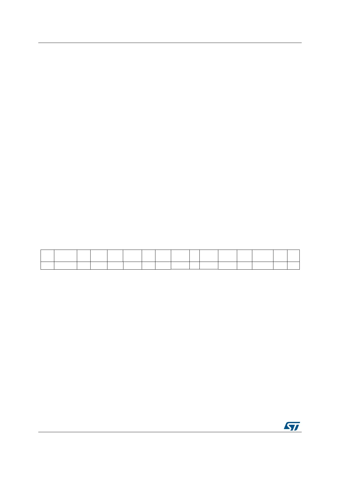
USB control register (USB_CNTR)
Address offset: 0x40
Reset value: 0x0003
15 14 13 12 11 10 9 8 7 6 5 4 3 2 1 0
CTR
M
PMAOVR
M
ERR
M
WKUP
M
SUSP
M
RESET
M
SOF
M
ESOF
M
L1REQ
M
Res
.
L1RESU
ME
RE
SUME
F
SUSP
LP_
MODE
PDW
N
F
RES
rw rw rw rw rw rw rw rw rw rw rw rw rw rw rw
Bit 15 CTRM: Correct transfer interrupt mask
0: Correct Transfer (CTR) Interrupt disabled.
1: CTR Interrupt enabled, an interrupt request is generated when the corresponding bit in the
USB_ISTR register is set.
Bit 14 PMAOVRM: Packet memory area over / underrun interrupt mask
0: PMAOVR Interrupt disabled.
1: PMAOVR Interrupt enabled, an interrupt request is generated when the corresponding bit
in the USB_ISTR register is set.
Bit 13 ERRM: Error interrupt mask
0: ERR Interrupt disabled.
1: ERR Interrupt enabled, an interrupt request is generated when the corresponding bit in
the USB_ISTR register is set.
Bit 12 WKUPM: Wakeup interrupt mask
0: WKUP Interrupt disabled.
1: WKUP Interrupt enabled, an interrupt request is generated when the corresponding bit in
the USB_ISTR register is set.

 Loading...