RM0440 Rev 4 953/2126
RM0440 High-resolution timer (HRTIM)
1083
Synchronization, counter reset, start and reset-start events are discarded in debug mode,
as well as capture events. This is to keep all related registers stable as long as the MCU is
halted.
The counter stops counting when a breakpoint is reached. However, the counter enable
signal is not reset; consequently no start event is emitted when exiting from debug. All
counter reset and capture triggers are disabled, as well as external events (ignored as long
as the MCU is halted). The outputs SET and RST flags are frozen, except in case of forced
software set/reset. A level-sensitive event is masked during the debug but is active again as
soon as the debug is exited. For edge-sensitive events, if the signal is maintained active
during the MCU halt, a new edge is not generated when exiting from debug.
The update events are discarded. This prevents any update trigger on hrtim_upd_en[3:1]
inputs. DMA triggers are disabled. The burst mode circuit is frozen: the triggers are ignored
and the burst mode counter stopped.
DLL calibration is not blocked while the MCU is halted (the DLLRDY flag can be set).
27.4 Application use cases
27.4.1 Buck converter
Buck converters are of common use as step-down converters. The HRTIM can control up to
12 buck converters with 7 independent switching frequencies.
The converter usually operates at a fixed frequency and the Vin/Vout ratio depends on the
duty cycle D applied to the power switch:.
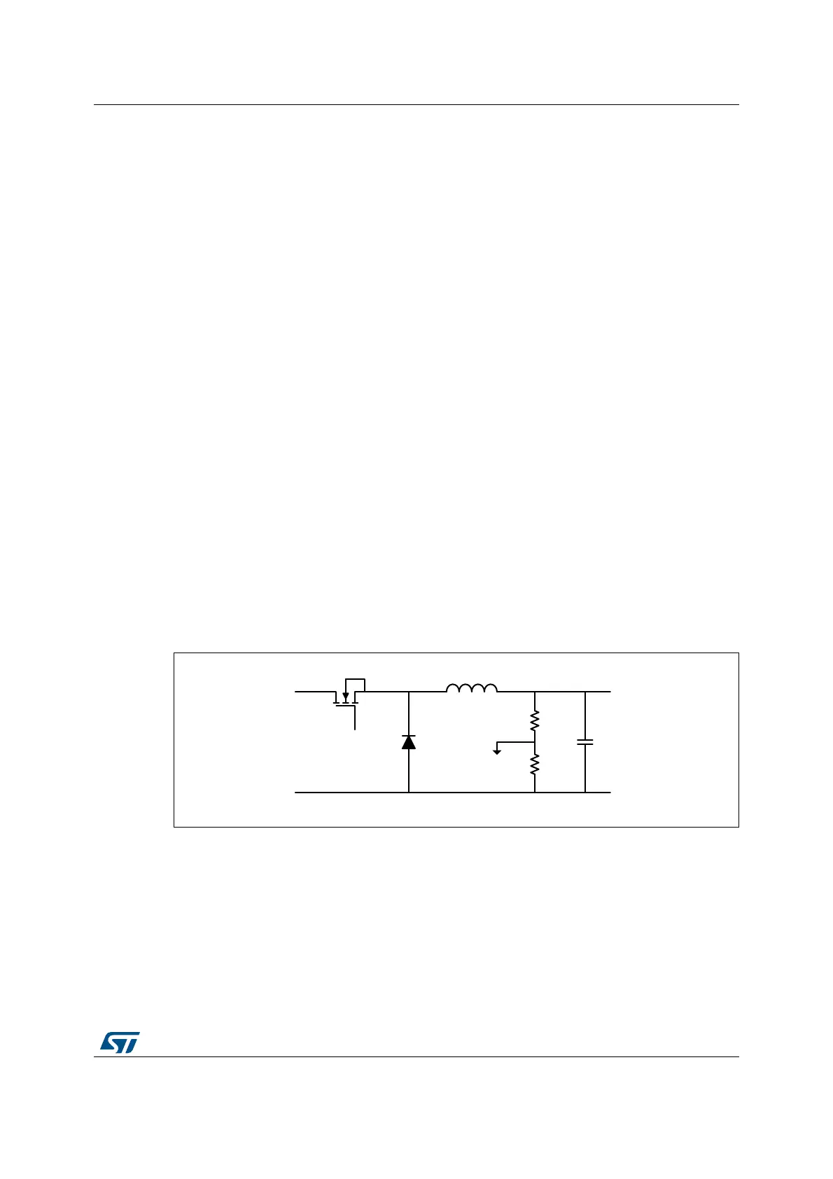
The topology is given on Figure 261 with the connection to the ADC for voltage reading.
Figure 261. Buck converter topology
Figure 262 presents the management of two converters with identical frequency PWM
signals. The outputs are defined as follows:
• HRTIM_CHA1 set on period, reset on CMP1
• HRTIM_CHA2 set on CMP3, reset on PER
The ADC is triggered twice per period, precisely in the middle of the ON time, using CMP2
and CMP4 events.
MS32343V3
HRTIM_
CHA1
V
IN
V
OUT
ADC
 Loading...


