VM15 User Manual Description of Display and Symbols
31
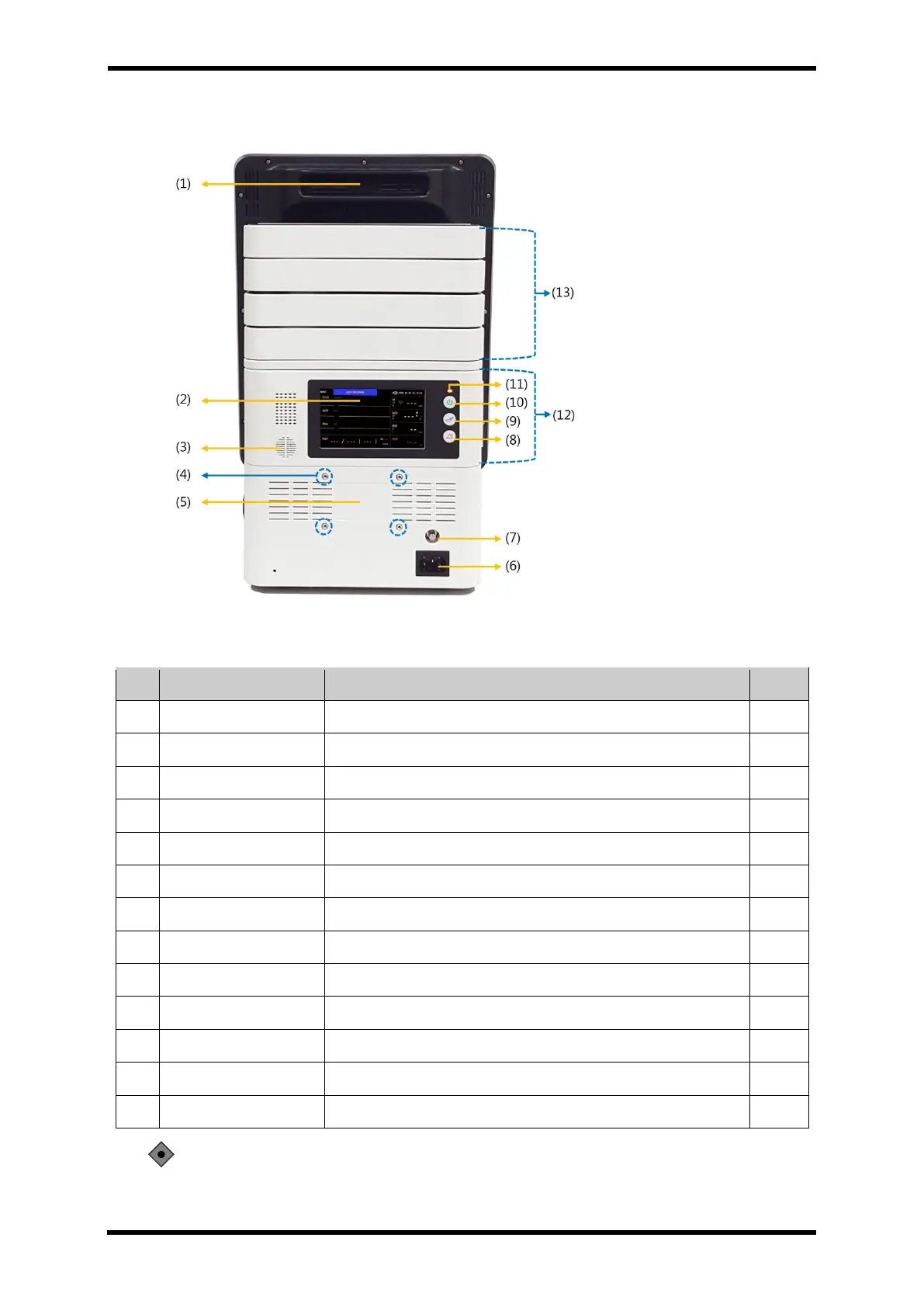
Rear Panel Components – STD1
Figure 6-2. Rear Panel Controls and Display – STD1
Table 6-3. Rear Panel Description – STD1
Sound measurement information
Screw hole for wall mount connection
Connector for input of commercial power
Terminal for connecting ground wire
Pause the alarm sound when an alarm condition occurs
Button to start/stop non-invasive blood pressure measurement
Turn the operation On / Off.
Standard module box connection part
Port that connects the option module box
CAUTION: Please do not on or off the power supply when the main monitor (front panel)
and Transport Module (rear panel) is separated. It may cause the malfunction.