VM15 User Manual Explanation of ICO (Option)
159
How to connect the Patient
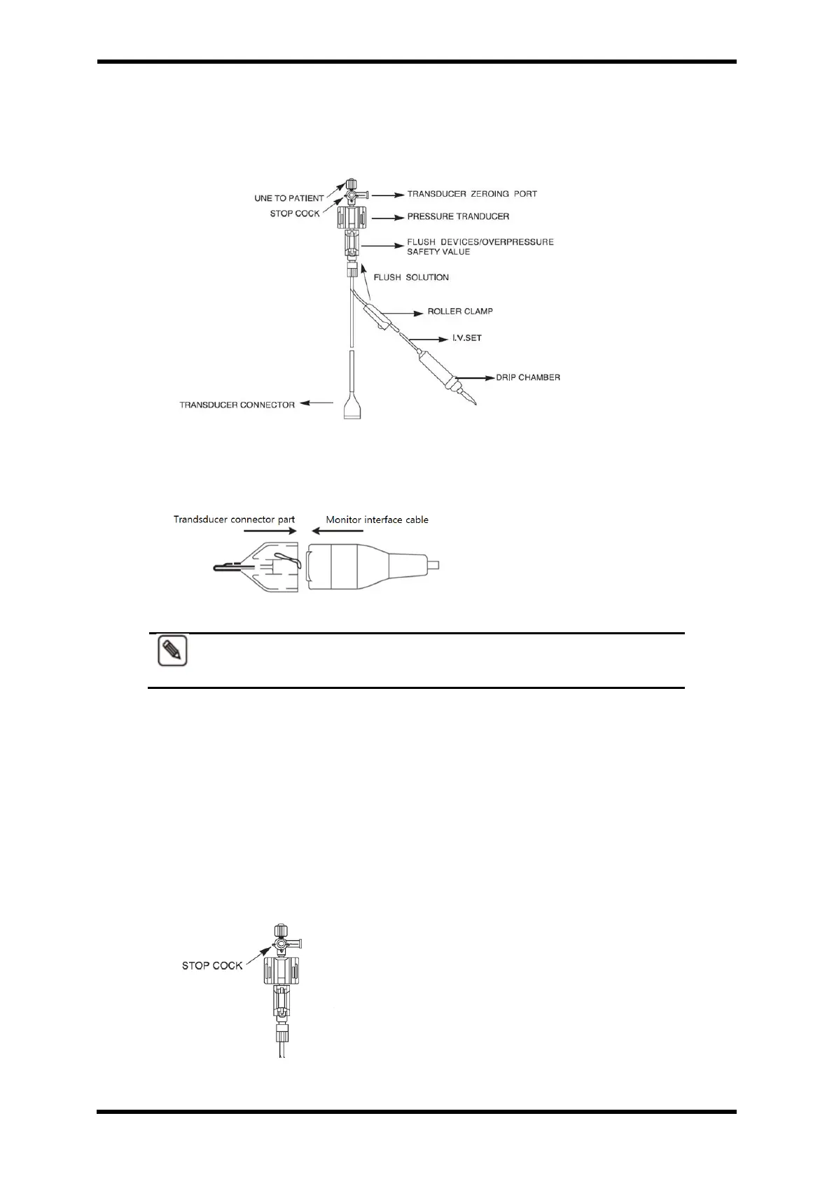
I. The below picture is IBP Sensor Cable Configuration
Figure 23-3. IBP Sensor Cable Configuration
II. The rear part of the transparent covering transducer connector and locate it with
the same position of the lot part of monitor interface cable. Then insert softly.
Figure 23-4. Monitor Interface Cable
To disconnect the IBP Sensor Cable, press the tap inside of transparent
cover covering transducer connector.
III. Stop cock
⚫ Open the package in clean area.
Check all connection is clear.
⚫ Check “STOP COCK’ handle in right position.
⚫ All of side port is protected with outlet cover. Do not remove it until the system is
full and the bubble is removed. The outlet cover should be replaced by outlet
cover. (IBP Kit includes pouch.)
Figure 23-5. Stop Cock