10-2 Xerox Internal Use Only Phaser 6000/6010 and WC 6015 MFP
Wiring
Wiring Diagrams
Notations Used in the Wiring Diagrams
The following table lists the symbols used in the wiring diagrams.
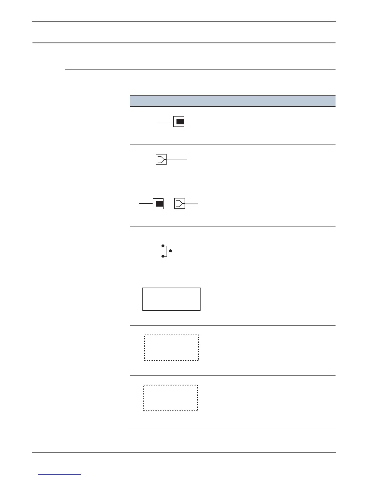
Symbol Description
Denotes a Plug.
Denotes a Jack.
Denotes Pin yy and Jack yy of the connector
Pxx and Jxx.
Denotes a Jumper Point (JPxxx/xxx). Each end
of the Jumper connection has a numeric
designation.
Denotes the parts.
PL X.Y.Z implies the item “Z” of plate (PL) “X.Y”
in Parts List.
Denotes functional parts attached with
functional parts name.
Denotes the control and its outline in the
Board.
Jack
P/Jxx
YY
Plug and Jack
Fuser
PL X.Y.Z
Subassembly 1
Heater
Subassembly 2
 Loading...


