4.7 Auto-Tuning
122 YASKAWA ELECTRIC SIEP C710616 27G YASKAWA AC Drive A1000 Technical Manual
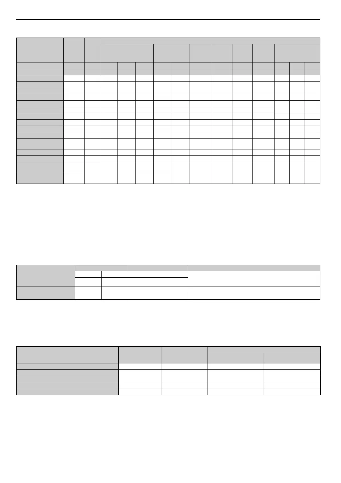
Table 4.24 Auto-Tuning Input Data
Inertia Tuning and Speed Control Loop Auto-Tuning
Inertia Tuning can be performed when the drive is using Closed Loop Vector control for either IM or PM motors. Inertia
Tuning automatically calculates load and motor inertia, and optimizes settings related to the KEB Ride-Thru function
(KEB 2) and Feed Forward control.
ASR Gain Auto-Tuning performs the same operat
ion as Inertia Tuning, but also optimizes speed control loop settings.
Table 4.25 Inertia and Speed Control Loop Tuning
Note: Inertia Tuning and ASR Gain Auto-Tuning might not be available if gears are between the machine and the motor shaft.
Table 4.26 explains that data that must be entered in order to perform the Inertia Tuning and ASR Gain Auto-Tuning.
Refer to Auto-Tuning for Permanent Magnet Motors on page 121 for details.
Table 4.26 Auto-Tuning Input Data
Input Value
<1> Input the motor code when using the YASKAWA motor. Select FFFF when using the motor by other manufacturers.
<2> Input data is needed for CLV/PM only.
<3> Depends on T2-13 setting.
Input
Parameter
Unit
Tuning Type (T2-01)
0
Motor Parameter Settings
1
Stationary
2
Stationary
Stator
Resistance
3
Z-Pulse
Offset
11
Back EMF
Constant
13
High
Frequency
Injection
14
Rotational
Control Mode A1-02 – 5, 6, 7 5 6, 7 5 6, 7 5, 6, 7 7 7 6, 7 5 6 7
Motor Code T2-02 – <1> FFFF FFFF – – – – – – – – –
Motor Type T2-03 – N/A N/A N/A YES YES N/A N/A N/A N/A YES YES YES
Motor rated power T2-04 kW N/A YES YES YES YES N/A N/A N/A N/A YES YES YES
Motor rated voltage T2-05 Va c N/A YES YES YES YES N/A N/A N/A N/A YES YES YES
Motor rated current T2-06 A N/A YES YES YES YES YES N/A N/A N/A YES YES YES
Motor rated frequency T2-07 Hz N/A YES N/A YES N/A N/A N/A N/A N/A YES N/A N/A
Number of motor poles T2-08 – N/A YES YES YES YES N/A N/A N/A N/A YES YES YES
Motor rated Speed T2-09
min
-1
N/A N/A YES N/A YES N/A N/A N/A N/A N/A YES YES
Stator 1 Phase resistance T2-10 YES YES YES N/A N/A N/A N/A N/A N/A N/A N/A N/A
d-axis inductance T2-11 mH YES YES YES N/A N/A N/A N/A N/A N/A N/A N/A N/A
q-axis inductance T2-12 mH YES YES YES N/A N/A N/A N/A N/A N/A N/A N/A N/A
Induced Voltage constant
Unit Selection
T2-13 – YES YES YES N/A N/A N/A N/A N/A N/A N/A N/A
N/A
Voltage constant T2-14 <3> YES YES YES N/A N/A N/A N/A N/A N/A N/A N/A N/A
Tuning pull-in current T2-15 % N/A N/A N/A YES YES N/A N/A N/A N/A YES YES YES
PG Number of pulses per
revolution
T2-16 – YES <2> N/A YES <2> N/A YES <2> N/A N/A N/A N/A N/A N/A YES
Z Pulse Offset T2-17
deg
(mech.)
YES
<2> N/A YES <2> N/A YES <2> N/A N/A N/A N/A N/A N/A N/A
Type Setting Control Mode Application Conditions and Benefits
Inertia Tuning
IM Motor T1-01 = 8 CLV Lets the motor rotate at a certain speed and appli
es a test signal. The response to
the test signals are analyzed, and adjustments are made to parameters controlling
the Feed Forward and KEB Ride-Thru functions (KEB 2, L2-29 = 1).
PM Motor T2-01 = 8
CLV/PM
ASR Gain Auto-Tuning
IM Motor T1-01 = 9 CLV
Performs the same operation as Inertia T
uning, but also adjusts the ASR gain
according to the response to the test signal.
PM Motor T2-01 = 9 CLV/PM
Input Value Input Parameter Unit
Tuning Type (T1-01 or T2-01)
8
Inertia Tuning
9
ASR Gain Tuning
Control Mode A1-02 – 3, 7 3, 7
Test signal frequency T3-01 Hz YES YES
Test signal Amplitude T3-02 rad YES YES
Motor inertia T3-03
kgm
2
YES YES
System response frequency T3-04 Hz N/A YES
 Loading...


