5.2 b: Application
168 YASKAWA ELECTRIC SIEP C710616 27G YASKAWA AC Drive A1000 Technical Manual
I Control
The output of I control is the integral of the deviation. It minimizes the offset between target and feedback value that
typically remains when pure P control is used. The integral time (I time) constant determines how fast the offset is
eliminated.
D Control
D control predicts the deviation signal by multiplying its derivative (slope of the deviation) with a time constant, then
adds this value to the PID input. This way the D portion of a PID controller provides a braking action to the controller
response and can reduce the tendency to oscillate and overshoot.
Be aware that D control tends to amplify noise on
the deviation signal, which can result in control instability. D control
should therefore only be used when necessary.
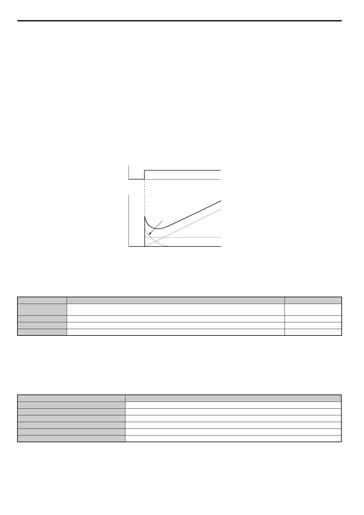
PID Operation
To better demonstrate how PID works, Figure 5.25 shows how the PID output changes when the PID input (deviation)
jumps from 0 to a constant level.
Figure 5.25
Figure 5.25 PID Operation
Using PID Control
Applications for PID control are listed in Table 5.8.
Table 5.8 Using PID Control
PID Setpoint Input Methods
The PID setpoint input can be input from one of the sources listed in Table 5.9.
If none of the sources listed in Table 5.9 are used, the frequency reference source in b1
-01 (or b1-15) or one of the inputs
listed in Table 5.9 becomes the PID setpoint.
Table 5.9 PID Setpoint Sources
Note: A duplicate allocation of the PID setpoint input will cause an oPE07 (Multi-Function Analog Input Selection Error) alarm.
Application Description Sensors Used
Speed Control
Machinery speed is fed back and adjusted to meet the target value. Synchronous control is performed using speed data from
other machinery as the target value
Tachometer
Pressure Maintains constant pressure using pressure feedback. Pressure sensor
Fluid Control Keeps flow at a constant level by feeding back flow data. Flow rate sensor
Temperature Control Maintains a constant temperature by controlling a fan with a thermostat. Thermocoupler, Thermistor
PID Setpoint Source Settings
Analog Input A1 Set H3-02 = C
Analog Input A2 Set H3-10 = C
Analog Input A3 Set H3-06 = C
MEMOBUS/Modbus Register 0006H Set bit 1 in register 000FH to 1 and input the setpoint to register 0006H
Pulse Input RP Set H6-01 = 2
Parameter b5-19 Set parameter b5-18 = 1 and input the PID setpoint to b5-19
PID input
I control
PID Output
D control
Time
PID output
Time
P control