5.8 L: Protection Functions
272 YASKAWA ELECTRIC SIEP C710616 27G YASKAWA AC Drive A1000 Technical Manual
L1-09: OL1 Current Lvl (for 2nd motor)
Sets the reference current for motor thermal overload detection for motor 2 in amperes.
If L1-09 is set to 0.0A, E4-01 is used as a reference for
motor overload protection. If L1-09 is set to any other, that value
is used as a reference for motor overload protection.
Note: This parameter is not available in models CIMR-A4A0930 and 4A1200.
L1-13: Continuous Electrothermal Operation Selection
Determines whether or not to hold the current value of the electrothermal motor protection (L1-01) when the power
supply is interrupted.
Setting 0: Disabled
Setting 1: Enabled
Motor Protection Using an NTC Thermistor Input
Motor protection is possible for models CIMR-A4A0930 and 4A1200 by connecting the NTC thermistor input in the
motor windings to one of the drive analog input terminals. This enables the drive to provide torque compensation in
response to changes in motor temperature and protect the motor from overheating.
Note: This parameter is available in models CIMR-A4A0930 and 4A1200.
If the NTC input signal using the drive multi-function analog input terminal exceeds the overheat alarm level set to
L1-16 (or L1-18 for motor 2), then oH5 will flash on the digital operator screen. The drive will respond to the alarm
according to the setting of L1-20 (default setting is to continue operation when an oH5 alarm occurs).
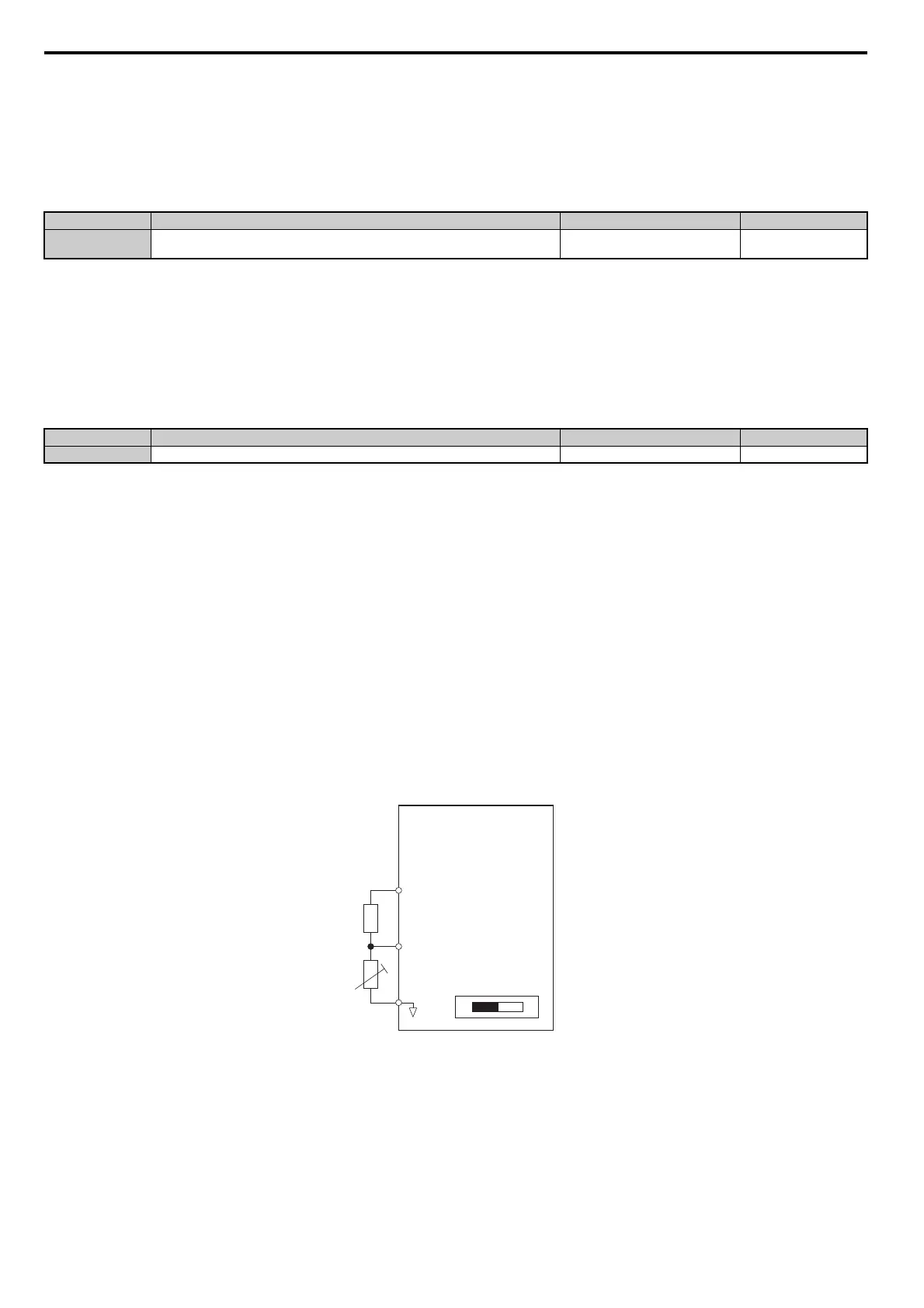
Figure 5.93 shows a circuit using the NTC thermistor and the termina
l resistance values. Set DIP switch S1 on the drive
to “V” for voltage input when wiring the NTC thermistor input to
terminal A2 on the drive.
Note: This example assumes that H3-10 = 17, H3-09 = 0, and DIP switch S1 has been set for voltage input.
Figure 5.93
Figure 5.93 Motor Protection Circuit using NTC Input
No. Name Setting Range Default
L1-09
<1> Display is in the following units.
CIMR-A2A0004 to 2A0040, CIMR-A4A0002 to 4A0023: 0.01 A units
CIMR-A2A0056 to 2A0312, CIMR-A4A0031 to 4A0675: 0.1 A units
<2> Cannot be set to a value smaller than 10% of drive rated current if the current level is set to a value greater than 0.0 A.
OL1 Current Lvl (for 2nd motor)
0.0 A or 10 to 150% of drive rated
current <1> <2>
0.0 A
No. Name Setting Range Default
L1-13 Continuous Electrothermal Operation Selection 0 or 1 1
+V
(+10.5 V, 20 mA)
Voltage Divider
2 kΩ
NTC Thermistor
A2 (0-10 V)
DIP Switch S1
AC
VI
Drive
 Loading...


