5.8 L: Protection Functions
278 YASKAWA ELECTRIC SIEP C710616 27G YASKAWA AC Drive A1000 Technical Manual
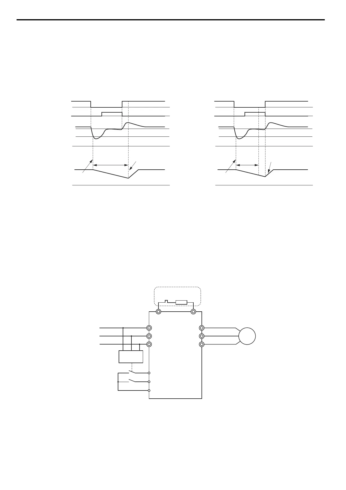
KEB Ride-Thru Operation as Long as CPU Has Power, KEB Input Used
Here, L2-01 = 3 and an input terminal is set to issue KEB Ride-Thru (H1- = 65, 66, 7A, 7B). After decelerating for
the time set in parameter L2-10, the drive checks the DC bus voltage and the status of the digital input. If the DC bus
voltage is still below the level set in L2-11 or if the digital input assigned to KEB Ride-Thru is still active, then the drive
continues to decelerate. If the DC bus voltage has risen above L2-11 and the terminal that initiated KEB Rid-Thru is
released, then operation resumes.
Figure 5.99
Figure 5.99 KEB Operation Using L2-10 and KEB Input
L2-01 = 5
KEB operation ends when the motor has come to a stop, even if the power returns and the digital input terminal that
initiated KEB Ride-Thru is cleared.
KEB Operation Wiring Example
Figure 5.100 shows a wiring example for triggering the KEB Ride-Thru at power loss using an undervoltage relay. If
power loss occurs, the undervoltage relay triggers KEB Ride-Thru at terminal S6 (H1-06 = 65, 66, 7A, 7B). Note that an
ad
ditional dynamic braking option is required if System KEB Ride-Thru 1 is used.
Note: 1. Make sure the Run command is not switched off during momentary power loss. If the Run command is shut off, the drive will not
accelerate back to speed when the power is restored.
2. A dynamic braking option is required in order to use System KEB 1 (L2-29 = 2).
Figure 5.100
Figure 5.100 KEB Function Wiring Example
L2-11 (Desired DC Bus Voltage)
DC bus voltage
KEB Digital Input
Main Power Supply
Output Frequency
L2-05 (Uv Detection Level)
0 Hz
0 V
0 V
KEB deceleration is
triggered by DC bus voltage
KEB restart after
L2-02 has passed
Power Loss
Power loss longer than L2-10Power loss shorter than L2-10
L2-10 (Minimum KEB
Operation Time)
L2-11 (Desired DC Bus Voltage)
L2-05 (Uv Detection Level)
0 Hz
0 V
0 V
KEB deceleration is
triggered by DC bus voltage
KEB restart after
L2-02 has passed
Power Loss
L2-10 (Min.
KEB
Operation
Time)
M
R/L1
S/L2
T/L3
U/T1
V/T2
W/T3
B1 B2
L1
L2
L3
Braking
Resistor
UV Detection
Relay
S6 - KEB command 1 or 2
S1 - Start command
SC
Required for System KEB
Ride-Thru 1 only (L2-29 = 2)