5.8 L: Protection Functions
YASKAWA ELECTRIC SIEP C710616 27G YASKAWA AC Drive A1000 Technical Manual 279
Parameters for KEB Ride-Thru
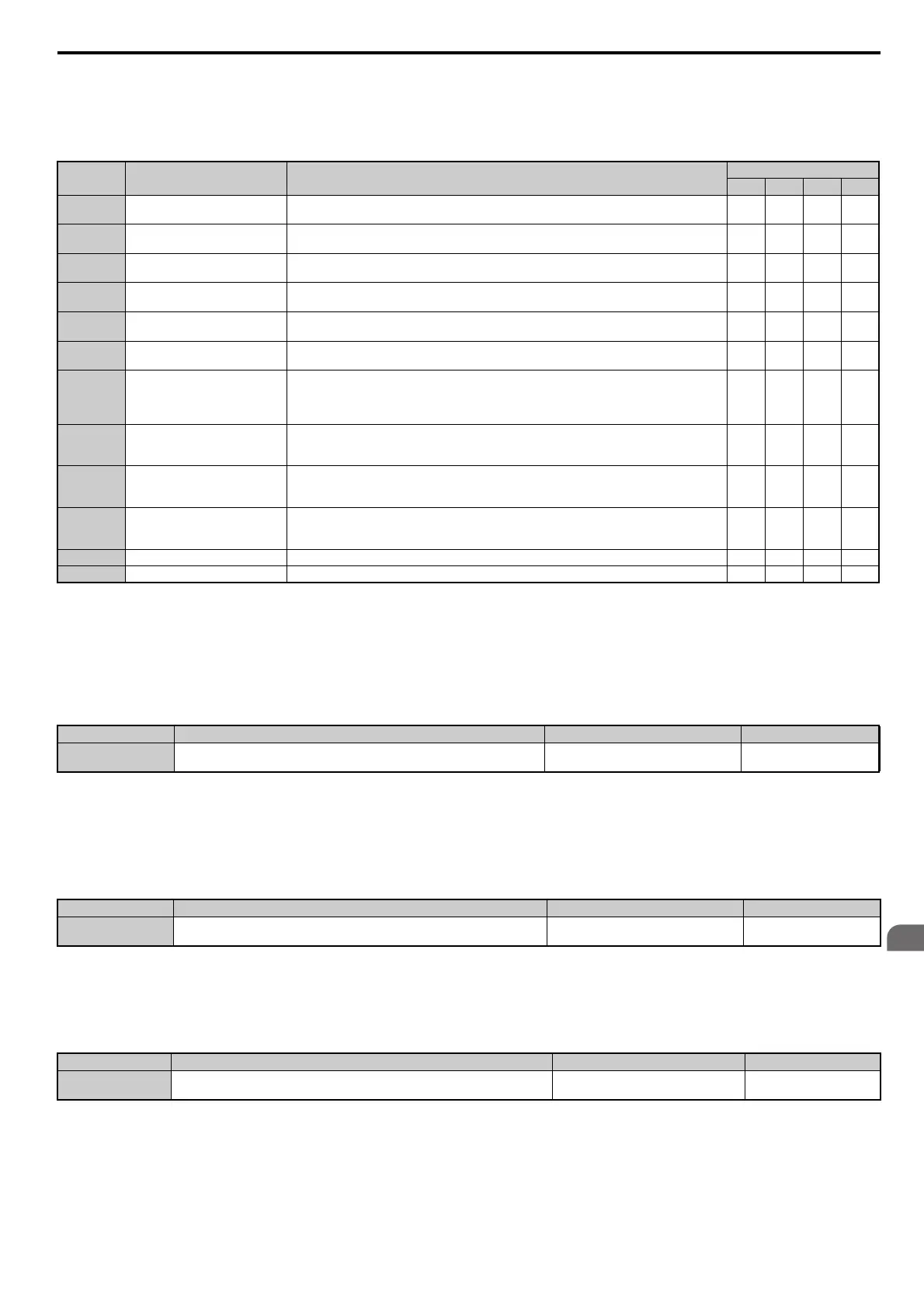
Table 5.42 lists parameters needed to set up KEB Ride-Thru depending the type of KEB Ride-Thru selected in L2-29.
Table 5.42 KEB Function Related Adjustments
L2-02: Momentary Power Loss Ride-Thru Time
Sets the maximum time allowed to ride through a power loss. If power loss operation exceeds this time, the drive will
attempt to accelerate back to frequency reference. This parameter is valid if L2-01 = 1 or 3.
Note: The amount of time the drive is capable of recovering after a power loss is determined by the capacity of the drive. Drive
capacity determines the upper limit for L2-02.
L2-03: Momentary Power Loss Minimum Baseblock Time
Sets the minimum baseblock time when power is restored following a momentary power loss. This determines the time
the drive waits for the residual voltage in the motor to dissipate. Increase this setting if overcurrent or overvoltage occurs
at the beginning of Speed Search, after a power loss, or during DC Injection Braking.
L2-04: Momentary Power Loss Voltage Recovery Ramp Time
Sets the time for the drive to restore the output voltage to the level specified by the V/f pattern after Speed Search. The
setting value determines the time for the voltage to go from 0 V to the maximum voltage.
Parameter Name Setting Instructions
KEB Mode (L2-29)
0 1 2 3
C1-09 Fast Stop Time
• Increase if an overvoltage fault (ov) occur during KEB decel
eration.
• Decrease if an undervoltage fault (Uv1) occurs d
uring KEB deceleration.
YES NO NO
NO
C2-03 S-Curve at Deceleration Start
• Shorten if undervoltage (Uv1) occurs rig
ht after KEB Ride-Thru is triggered.
• Lengthen this setting if overvoltage occurs right after KEB operation starts.
YES NO YES
YES
L2-05 Undervoltage Detection Level
Increase if an undervoltage faul
t (Uv1) fault occurs at KEB operation start in order to let the drive
detect power loss more quickly.
YES YES YES
YES
L2-06 KEB Deceleration Time
• Increase if an overvoltage fault (ov) occur during KEB decel
eration
• Decrease if an undervoltage fault (Uv1) occurs d
uring KEB deceleration
NO NO YES
YES
L2-07 KEB Acceleration Time
Adjust to the desired acceleration time. If set to 0, standard ac
celeration times are used (C1-01,
C1-03, C1-05, C1-07).
YES YES YES YES
L2-08 Frequency Gain at KEB Start
• Increase if an undervoltage fault occurs ri
ght after KEB operation starts.
• Decrease if an overvoltage fault
occurs right after KEB operation starts.
YES NO YES
YES
L2-10 KEB Detection Time
• Increase when a digital input is set for KEB Ride-Thru and
an undervoltage fault occurs after
power was lost because the device that controls the input does not react quickly enough.
• If the DC bus voltage overshoots after KEB Ride-Thru
begins (and no input terminal is set to
KEB Ride-Thru), increase L2-10 to longer than the overshoot.
YES YES YES
YES
L2-11
Desired DC Bus Voltage
duri
ng KEB
• Set to around 1.22 times the input voltage for Single Drive KEB Ride-Thru 2.
• Set to around 1.4 times the input voltage for Sin
gle Drive KEB Ride-Thru 1 and System KEB
Ride-Thru modes.
YES YES YES YES
L3-20 Main Circuit Adjustment Gain
• Increase this setting slowly in steps of 0.1 if overvo
ltage (ov) or undervoltage (Uv1) occurs at the
beginning of deceleration
• Reduce if torque ripple occurs during d
eceleration while executing KEB Ride-Thru.
NO YES NO
NO
L3-21
Accel/Decel Rate
Ca
lculation Gain
• Reduce L3-21 in steps of 0.05 if there is a fairly large speed or current ripple.
• Decreasing this setting too much can result in a s
low DC bus voltage control response, and may
lead to problems with overvoltage or undervoltage.
NO YES NO NO
L3-24 Motor Acceleration Time Set the motor acceleration time as described on page 287. NO YES NO NO
L3-25 Load Inertia Ratio Set the load/inertia ratio as described on page 287. NO YES NO NO
No. Name Setting Range Default
L2-02 Momentary Power Loss Ride-Thru Time 0.0 to 25.5 s
Determined by C6-01 and
o2-04
No. Name Setting Range Default
L2-03 Momentary Power Loss Minimum Baseblock Time 0.1 to 5.0 s
Determined by C6-01
and o2-04
No. Name Setting Range Default
L2-04 Momentary Power Loss Voltage Recovery Ramp Time 0.0 to 5.0 s
Determined by C6-01 and
o2-04