8.4 Option Card Installation
420 YASKAWA ELECTRIC SIEP C710616 27G YASKAWA AC Drive A1000 Technical Manual
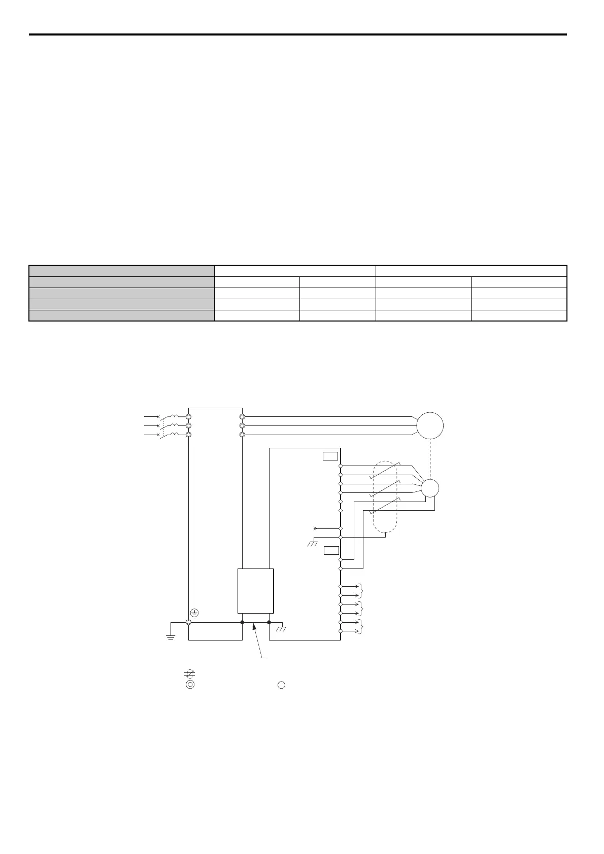
5. For the PG-B3 and PG-X3 Option, wire the motor PG encoder to the terminal block. Refer to Figure 8.8 and
Figure 8.12 for wiring instructions.
Refer to Terminal Functions on page 421 for a detailed description of the option terminal functions.
Connecting PG-B3 Option
Parameter Settings and Connections for Different Encoder Types
• Connecting a Single-Pulse Encoder
When using a single-pulse encoder in V/f with PG control mode, connec
t the pulse output from the PG to the option
and set drive parameter F1-21 to 0.
• Connecting a Two-Pulse Encoder
When using a two-pulse encoder, connect the A and B pulse outputs on the PG to
the option and set F1-21 to 1.
When using a two-pulse encoder in Closed Loop Vector control mode, connect pulse outputs A and B from the encoder
to the corresponding terminals on the option.
• Connecting a Two-Pulse Encoder with Z Marker Pulse
When using a two-pulse encoder with Z marker pulse, connect the
A, B, and Z pulse outputs to the corresponding
terminals on the option.
Connection Diagram of PG-B3
Refer to Table 8.3 for a detailed description of the option board terminal functions.
Refer to Wire Gauges and Tightening Torques on page 422 for information on making cables.
Figure 8.8 PG-B3 Option and Encoder Connection Diagram
Note: The
PG-B3 Option reads a maximum input frequency from the PG encoder of 50 kHz. Be sure to select an PG encoder with an
output pulse frequency of maximum 50 kHz when operating at maximum speed.
Control Method V/f with PG Closed Loop Vector
No. of Encoders 1 (CN5-C) 2 (CN5-B) 1 (CN5-C) 2 (CN5-B)
Single Pulse (A) F1-21 = 0 F1-37 = 0 N/A N/A
Two Pulse (AB Quadrature) F1-21 = 1 F1-37 = 1 No setting required No setting required
Two Pulse with Marker (ABZ) F1-21 = 1 F1-37 = 1 No setting required No setting required
<1> Ground the shield on the PG side and the drive side. If noise problems arise in the PG signal, remove the shield ground from one end of the
signal line or remove the shield ground connection on both ends.
Twisted-pair shielded line
Main circuit terminal
Control circuit terminal
M
A+
A
B
Z
B+
Z+
AO
IG
BO
IG
ZO
IG
FE
IP
IG
TB1
SD
TB2
NC
CN5
PGB3
Option
U/T1
V/T2
W/T3
R/L1
S/L2
T/L3
FE
YASKAWA
Drive
Ground wire
A pulse monitor signal
B pulse monitor signal
Z pulse monitor signal
PG
3
4
5
6
E
1
2
<1>

 Loading...


