8.5 Installing Peripheral Devices
428 YASKAWA ELECTRIC SIEP C710616 27G YASKAWA AC Drive A1000 Technical Manual
Installing a Braking Resistor Unit: LKEB type
LKEB type braking resistors provide dynamic braking capability with up to 10% ED. They can be directly connected to
the drives B1 and B2 terminals as shown in Figure 8.19. The LKEB unit has a thermal overload cont
act that should be
utilized in order to switch off the drive in cas
e braking resistor overheat occurs.
As the drives internal braking resistor overload protection cannot protect LKEB
resistors, disable this function by setting
L8-01 to 0.
Figure 8.17
Figure 8.19 Connecting a Braking Resistor Unit: LKEB Type
(CIMR-A2A0004 to 2A0138, 4A0002 to 4A0072)
Installing Other Types of Braking Resistors
When installing braking resistors other than the ERF or LKEB types, make sure that the drive internal braking transistor
will not be overloaded with the required duty cycle and the selected resistance value. Use a resistor that is equipped with
a thermal overload relay contact, and utilize this contact to switch off the drive in case of braking resistor overheat.
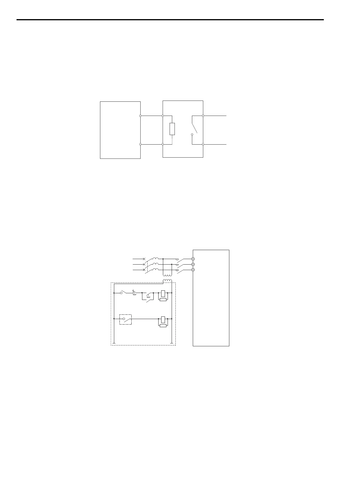
Braking Resistor Overload Protection
If using a braking resistor option, a sequence such as the one shown in Figure 8.20 should be set up to interrupt the
power supply in case the braking resistor
overheats.
Figure 8.18
Figure 8.20 Power Supply Interrupt for Overheat Protection (Example)
WARNING! Fire Hazard. Set up the sequence to shut off the power at the thermal relay trip contact on the braking resistor unit, as
shown in Figure 8.20, to protect the braking resistor unit from overheating.
If the power was shut off, turn the power back on after identifying the cause of the problem. Disconnect the braking resistor unit if the
power needs to be turned on to investigate the cause of the problem.
Braking Resistor Unit
(LKEB type)
Thermal Relay
Trip Contact
B1
B2
P1
B2
Drive
Drive
MC
Circuit Breaker
R
S
T
R/L1
S/L2
T/L3
SA
SA
400/200V
MCON
MC
OFF
THRX
THRX
Braking Resistor Unit
(Close: Overheat)
12