8.5 Installing Peripheral Devices
YASKAWA ELECTRIC SIEP C710616 27G YASKAWA AC Drive A1000 Technical Manual 429
Peripheral Devices &
Options
8
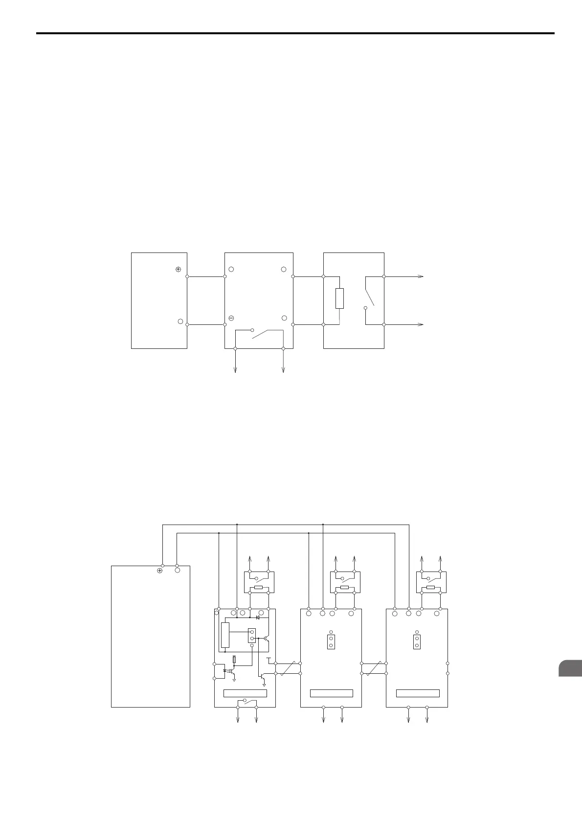
Installing a Braking Unit: CDBR Type
To install a CDBR type braking unit, connect the drive’s B1 terminal (CIMR-A2A0004 through 2A0138 and
CIMR-A4A0002 through 4A0072) or +3 terminal (CIMR-A2A0169 to 2A0415 and CIMR-A4A0088 to 4A1200)
to the positive terminal on the braking unit. Next wire the negative terminals on the drive and braking unit together.
Terminal +2 is not used.
Connect the braking resistor to the
CDBRs terminals +0 and -0.
Wire the thermal overload relay contact of the CDBR and the braking re
sistor in series, and connect this signal to a
circuit that disconnects the main input power supply to the drive in the event of a CDBR or braking resistor overload.
Disable dynamic braking transistor protecti
on by setting L8-55 = 0.
Note: To install a CDBR type braking unit to the drive with built-in dynamic braking transistor (CIMR-A2A0004 through 2A0138
and CIMR-A4A0002 through 4A0072), connect the drive’s B1 terminal to the positive terminal on the braking unit. Next wire
the negative terminals on the drive and braking unit together. Terminal B2 is not used.
Figure 8.19
Figure 8.21 Connecting a Braking Unit (CDBR type) and Braking Resistor Unit (LKEB type)
(CIMR-A2A0169 to 2A0415, 4A0088 to 4A1200)
Using Braking Units in Parallel
When multiple braking units are used, they must be installed with a master-slave configuration with a single braking unit
acting as the master. Figure 8.22 illustrates how to wire braking units in parallel.
Wire the thermal overload contacts relays of all CDBRs and all
braking resistors in series, then connect this signal to a
drive digital input. This input can be used to trigger a fault in the drive in case of overload in any of the CDBRs or
braking resistors.
Figure 8.20
Figure 8.22 Connecting Braking Units in Parallel
Thermal Relay
Trip Contact
Drive
Braking Unit
(CDBR type)
Braking Resistor Unit
(LKEB type)
Thermal Overload
Protector Trip Contact
1
2
P
34
3 + + 0
−− 0
B
+
−
Drive
Braking Resistor
Overheat Contact
(Thermal Relay Trip Contact)
Braking Resistor
Overheat Contact
(Thermal Relay Trip Contact)
Braking Resistor
Overheat Contact
(Thermal Relay Trip Contact)
Braking
Resistor
Unit
Braking
Resistor
Unit
Braking
Resistor
Unit
Braking Unit 2
+15
5
1
2
6
SLAVE
MASTER
Level Detector
Cooling Fin Overheat Contact
(Thermoswitch Contact)
Cooling Fin Overheat Contact
(Thermoswitch Contact)
Cooling Fin Overheat Contact
(Thermoswitch Contact)
Braking Unit 3
Braking Unit 1
1
34
34 3
5
6
5
6
1
2
4
2
3
1
P
2
B
−
− 0+ 0+
−
+−+− + 0 − 0+ 0 − 0
BPBP
12 1 2
MASTER
SLAVE
MASTER
SLAVE
+