B.3 Parameter Table
YASKAWA ELECTRIC SIEP C710616 27G YASKAWA AC Drive A1000 Technical Manual 455
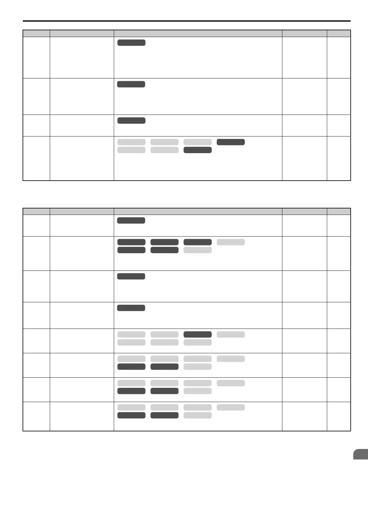
b2: DC Injection Braking and Short Circuit Braking
b1-15
(1C4H)
Frequency Reference Selection 2
Enabled when an input terminal set for “External reference” (H1- = 2) closes.
0: Digital operator
1: Terminals (analog input terminals)
2: MEMOBUS/Modbus communications
3: Option card
4: Pulse train input
Default: 0
Min: 0
Max: 4
157
b1-16
(1C5H)
Run Command Selection 2
Enabled when a terminal set for “External reference” (H1- = 2) closes.
0: Digital operator
1: Digital input terminals
2: MEMOBUS/Modbus communications
3: Option card
Default: 0
Min: 0
Max: 3
157
b1-17
(1C6H)
Run Command at Power Up
0: Disregarded. A new Run command needs to be issued after power up.
1: Allowed. Motor will start immediately after power up if a Run command is already enabled.
Default: 0
Min: 0
Max: 1
157
b1-21
(748H)
Start Condition Selection at Closed
Loop Vector Control
There is normally no need to change this parameter from the default value.
Selects a condition to start Closed Loop Vector Control.
0: Run command is not accepted when b2-01 Motor speed < E1-09.
1: Run command is accepted when b2-01 Motor speed < E1-09.
Note: This parameter is not available with models CIMR-A4A0930 and 4A1200.
Default: 0
Min: 0
Max: 1
157
<11> Setting range is 0, 1, or 3 when the control mode is CLV, OLV/PM, AOLV/PM, or CLV/PM.
No.(Addr.) Name Description Setting Page
b2-01
(189H)
<7> A coasting motor may require a braking resistor circuit to bring the motor to a stop in the required time.
<10> Default setting is determined by the control mode (A1-02).
DC Injection Braking Start
Frequency
Sets the frequency at which DC Injection Braking starts when “Ramp to stop” (b1-03 = 0) is
selected.
Default:
<10>
Min: 0.0 Hz
Max: 10.0 Hz
158
b2-02
(18AH)
DC Injection Braking Current
Sets the DC Injection Braking current as a percentage of the drive rated current.
Note: This parameter is not available for AOLV/PM with models CIMR-A4A0930 and
4A1200.
Default: 50%
Min: 0%
Max: 100%
159
b2-03
(18BH)
DC Injection Braking Time at Start
Sets the time of DC Injection Braking (Zero Speed Control when in CLV and CLV/PM) time at
start. Disabled when set to 0.00 s.
Note: This parameter is not available for AOLV/PM with models CIMR-A4A0930 and
4A1200.
Default: 0.00 s
Min: 0.00 s
Max: 10.00 s
159
b2-04
(18CH)
DC Injection Braking Time at Stop
Sets the time of DC Injection Braking (Zero Speed Control when in CLV and CLV/PM) at stop.
Note: This parameter is not available for AOLV/PM with models CIMR-A4A0930 and
4A1200.
Default:
<10>
Min: 0.00 s
Max: 10.00 s
159
b2-08
(190H)
Magnetic Flux Compensation
Va lu e
Sets the magnetic flux compensation as a percentage of the no-load current value (E2-03).
Default: 0%
Min: 0%
Max: 1000%
159
b2-12
(1BAH)
Short Circuit Brake Time at Start
Sets the time for Short Circuit Braking operation at start.
<7>
Default: 0.00 s
Min: 0.00 s
Max: 25.50 s
160
b2-13
(1BBH)
Short Circuit Brake Time at Stop
Sets the Short Circuit Braking operation time at stop.
<7>
Default: 0.50 s
Min: 0.00 s
Max: 25.50 s
160
b2-18
(177H)
Short Circuit Braking Current
Determines the current level for Short Circuit Braking. Set as a percentage of the motor rated
current.
Default: 100.0%
Min: 0.0%
Max: 200.0%
160
No.(Addr.) Name Description Setting Page
All Modes
All Modes
OLV/PM AOLV/PM
CLV
V/f w/PG
CLV/PM
V/f OLV
OLV/PM AOLV/PM
CLV
V/f w/PG
CLV/PM
V/f OLV
OLV/PM AOLV/PM
CLV
V/f w/PG
CLV/PM
V/f OLV
OLV/PM AOLV/PM
CLV
V/f w/PG
CLV/PM
V/f OLV
OLV/PM AOLV/PM
CLV
V/f w/PG
CLV/PM
V/f OLV
OLV/PM AOLV/PM
CLV
V/f w/PG
CLV/PM
V/f OLV
 Loading...


