B.3 Parameter Table
YASKAWA ELECTRIC SIEP C710616 27G YASKAWA AC Drive A1000 Technical Manual 485
43
FWD/REV Command (2-wire Sequence
2)
Open: Forward
Closed: Reverse
Note: Determines motor direction, but does not issue a Run command. Cannot be set together with settings 40 or
41.
242
44 Offset Frequency 1
Closed: Adds d7-01 to the frequency reference.
242
45 Offset Frequency 2
Closed: Adds d7-02 to the frequency reference.
242
46 Offset Frequency 3
Closed: Adds d7-03 to the frequency reference.
242
47 Node Setup
Closed: Node setup for SI-S3 enabled.
243
60 DC Injection Braking Command
Closed: Triggers DC Injection Braking.
243
61 External Speed Search Command 1
Closed: Activates Current Detection Speed Search from the maximum output frequency (E1-04).
243
62 External Speed Search Command 2
Closed: Activates Current Detection Speed Search from the frequency reference.
243
63 Field Weakening
Closed: The drive performs Field Weakening control as set for d6-01 and d6-02.
243
65 KEB Ride-Thru 1 (N.C.)
Open: KEB Ride-Thru 1 enabled
243
66 KEB Ride-Thru 1 (N.O.)
Closed: KEB Ride-Thru 1 enabled
243
67 Communications Test Mode
Tests the MEMOBUS/Modbus RS-485/422 interface. Displays “PASS” if the test completes successfully.
243
68 High Slip Braking (HSB)
Closed: Activates High Slip Braking to stop the drive during any Run command.
243
6A Drive Enable
Open: Drive disabled. If this input is opened during run, then the drive will stop as specified by b1-03.
Closed: Ready for operation.
243
71 Speed/Torque Control Switch
Open: Speed Control
Closed: Torque Control
244
72 Zero Servo
Closed: Zero Servo enabled
244
75 Up 2 Command
Used to control the bias added to the frequency reference by the Up/Down 2 function. The Up 2 and Down 2
commands must always be used in conjunction with one another.
244
76 Down 2 Command 244
77 ASR Gain Switch
Open: ASR proportional gain 1 (C5-01)
Closed: ASR proportional gain 2 (C5-03)
244
78
External Torque Reference Polarity
Inversion
Open: Forward torque reference
Closed: Reverse polarity
244
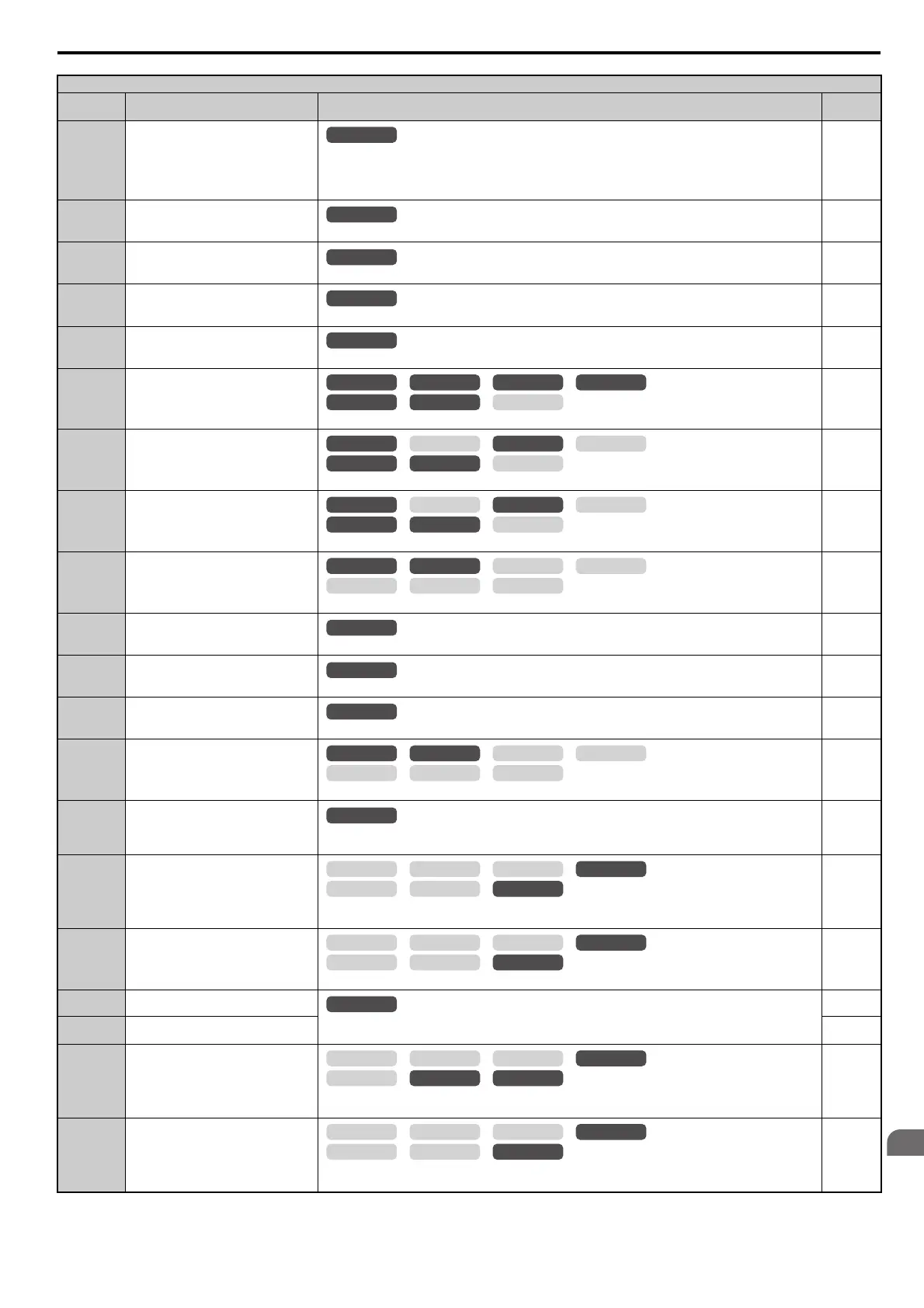
H1 Multi-Function Digital Input Selections
H1-
Setting
Function Description Page
OLV/PM AOLV/PM
CLV
V/f w/PG
CLV/PM
V/f OLV
OLV/PM AOLV/PM
CLV
V/f w/PG
CLV/PM
V/f OLV
OLV/PM AOLV/PM
CLV
V/f w/PG
CLV/PM
V/f OLV
OLV/PM AOLV/PM
CLV
V/f w/PG
CLV/PM
V/f OLV
OLV/PM AOLV/PM
CLV
V/f w/PG
CLV/PM
V/f OLV
OLV/PM AOLV/PM
CLV
V/f w/PG
CLV/PM
V/f OLV
OLV/PM AOLV/PM
CLV
V/f w/PG
CLV/PM
V/f OLV
OLV/PM AOLV/PM
CLV
V/f w/PG
CLV/PM
V/f OLV
OLV/PM AOLV/PM
CLV
V/f w/PG
CLV/PM
V/f OLV
 Loading...


