B.3 Parameter Table
486 YASKAWA ELECTRIC SIEP C710616 27G YASKAWA AC Drive A1000 Technical Manual
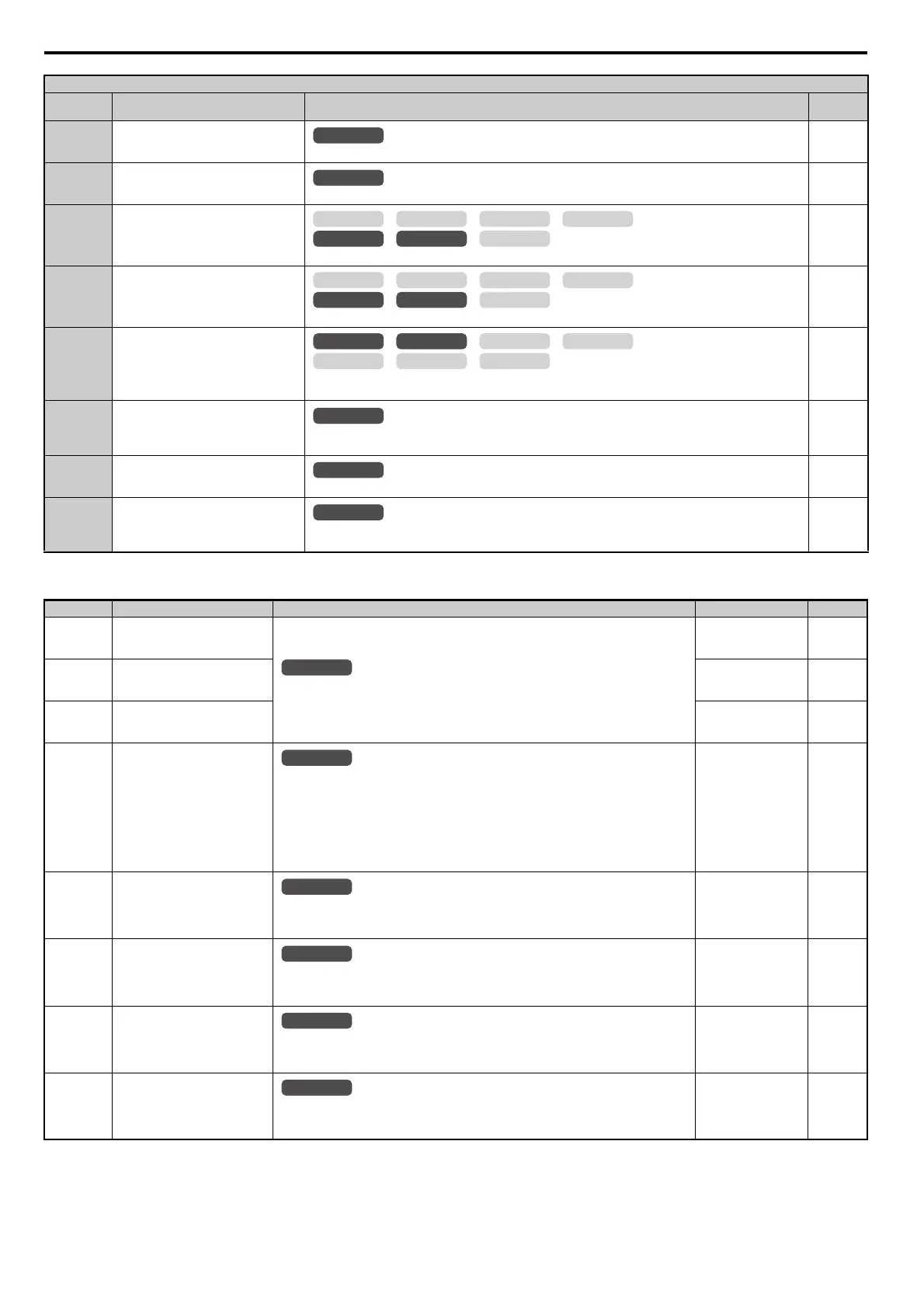
H2: Multi-Function Digital Outputs
7A KEB Ride-Thru 2 (N.C.)
Open: KEB Ride-Thru 2 enabled. Drive disregards L2-29 and performs Single Drive KEB Ride-Thru 2.
245
7B KEB Ride-Thru 2 (N.O.)
Closed: KEB Ride-Thru 2 enabled. Drive disregards L2-29 and performs Single Drive KEB Ride-Thru 2.
245
7C Short Circuit Braking (N.O.)
Closed: Short Circuit Braking enabled
245
7D Short Circuit Braking (N.C.)
Open: Short Circuit Braking enabled
245
7E Forward/Reverse Detection
Open: Forward motor operation is detected.
Closed: Reverse motor operation is detected.
245
7F Bi-Directional PID Output Selection
Open: Bi-directional output is disabled.
Closed: Bi-directional output is enabled.
245
90 to 97 DriveWorksEZ Digital Inputs 1 to 8
Reserved for DWEZ input functions
245
9F DriveWorksEZ Disable
Open: DWEZ enabled
Closed: DWEZ disabled
245
No.(Addr.) Name Description Setting Page
H2-01
(40BH)
Terminal M1-M2 Function
Selection (Relay)
Refer to H2 Multi-Function Digital Output Settings on page 487 for a description of setting
values.
Default: 0
Min: 0
Max: 192
246
H2-02
(40CH)
Terminal M3-M4 Function
Selection (Relay)
Default: 1
Min: 0
Max: 192
246
H2-03
(40DH)
Terminal M5-M6 Function
Selection (Relay)
Default: 2
Min: 0
Max: 192
246
H2-06
(437H)
Watt Hour Output Unit Selection
Sets the output units for the watt hours when Watt Hour Pulse Output is selected as the digital
output (H2-01, H2-02, or H2-03 = 39). Outputs a 200 ms pulse signal when the watt-hour
counter increases by the units selected.
0: 0.1 kWh units
1: 1 kWh units
2: 10 kWh units
3: 100 kWh units
4: 1000 kWh units
Default: 0
Min: 0
Max: 4
256
H2-07
(B3AH)
Memobus Regs1 Address Select Sets the addresses of the MEMOBUS/Modbus registers from which data will be sent to contact
outputs 62 and 162.
Note: This parameter is not available with models CIMR-A4A0930 and 4A1200.
Default: 1
Min: 1
Max: 1FFF
256
H2-08
(B3BH)
Memobus Regs1 Bit Select
Sets the bits for the MEMOBUS/Modbus registers from which data will be sent to contact
outputs 62 and 162.
Note: This parameter is not available with models CIMR-A4A0930 and 4A1200.
Default: 0
Min: 0
Max: FFFF
256
H2-09
(B3CH)
Memobus Regs2 Address Select
Sets the addresses of the MEMOBUS/Modbus registers from which data will be sent to contact
outputs 63 and 163.
Note: This parameter is not available with models CIMR-A4A0930 and 4A1200.
Default: 1
Min: 1
Max: 1FFF
256
H2-10
(B3DH)
Memobus Regs2 Bit Select
Sets the bits for the MEMOBUS/Modbus registers from which data will be sent to contact
outputs 63 and 163.
Note: This parameter is not available with models CIMR-A4A0930 and 4A1200.
Default: 0
Min: 0
Max: FFFF
256
H1 Multi-Function Digital Input Selections
H1-
Setting
Function Description Page
All Modes
OLV/PM AOLV/PM
CLV
V/f w/PG
CLV/PM
V/f OLV
OLV/PM AOLV/PM
CLV
V/f w/PG
CLV/PM
V/f OLV
OLV/PM AOLV/PM
CLV
V/f w/PG
CLV/PM
V/f OLV
All Modes
All Modes
All Modes
All Modes
All Modes
All Modes
All Modes
All Modes
 Loading...


