B.3 Parameter Table
492 YASKAWA ELECTRIC SIEP C710616 27G YASKAWA AC Drive A1000 Technical Manual
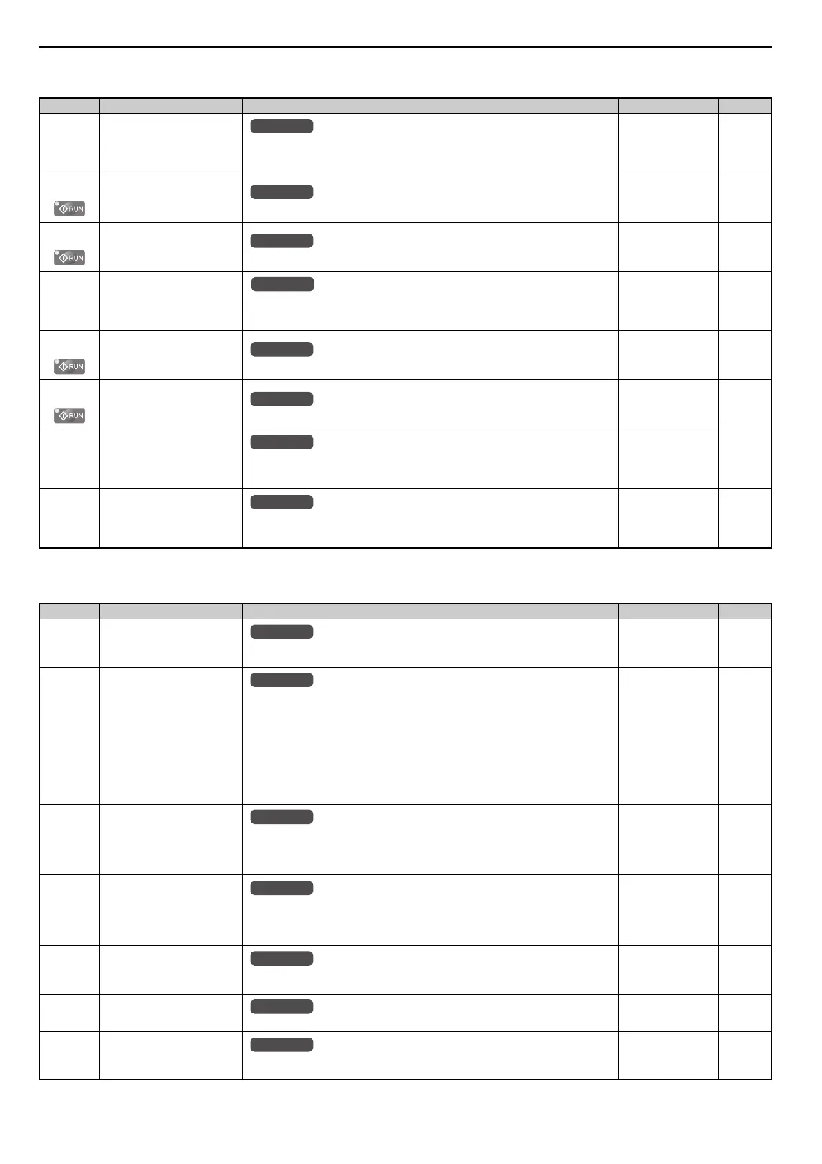
H4: Multi-Function Analog Outputs
H5: MEMOBUS/Modbus Serial Communication
Note: The settings for MEMOBUS/Modbus communications become effective when the drive is restarted.
No.(Addr.) Name Description Setting Page
H4-01
(41DH)
Multi-Function Analog Output
Terminal FM Monitor Selection
Selects the data to be output through multi-function analog output terminal FM.
Set the desired monitor parameter to the digits available in U-. For example, enter “103”
for U1-03.
Default: 102
Min: 000
Max: 999
262
H4-02
(41EH)
Multi-Function Analog Output
Terminal FM Gain
Sets the signal level at terminal FM that is equal to 100% of the selected monitor value.
Default: 100.0%
Min: -999.9%
Max: 999.9%
263
H4-03
(41FH)
Multi-Function Analog Output
Terminal FM Bias
Sets the signal level at terminal FM that is equal to 0% of the selected monitor value.
Default: 0.0%
Min: -999.9%
Max: 999.9%
263
H4-04
(420H)
Multi-Function Analog Output
Terminal AM Monitor Selection
Selects the data to be output through multi-function analog output terminal AM.
Set the desired monitor parameter to the digits available in U-. For example, enter “103”
for U1-03.
Default: 103
Min: 000
Max: 999
262
H4-05
(421H)
Multi-Function Analog Output
Terminal AM Gain
Sets the signal level at terminal AM that is equal to 100% of the selected monitor value.
Default: 50.0%
Min: -999.9%
Max: 999.9%
263
H4-06
(422H)
Multi-Function Analog Output
Terminal AM Bias
Sets the signal level at terminal AM that is equal to 0% of the selected monitor value.
Default: 0.0%
Min: -999.9%
Max: 999.9%
263
H4-07
(423H)
Multi-Function Analog Output
Terminal FM Signal Level
Selection
0: 0 to 10 V
1: -10 to 10 V
2: 4 to 20 mA
Default: 0
Min: 0
Max: 1
264
H4-08
(424H)
Multi-Function Analog Output
Terminal AM Signal Level
Selection
0: 0 to 10 V
1: -10 to 10 V
2: 4 to 20 mA
Default: 0
Min: 0
Max: 1
264
No.(Addr.) Name Description Setting Page
H5-01
(425H)
<32>
Drive Node Address
Selects drive station node number (address) for MEMOBUS/Modbus terminals R+, R-, S+, S-.
Cycle power for the setting to take effect.
Default: 1F
Min: 0
Max: FF
550
H5-02
(426H)
Communication Speed Selection
0: 1200 bps
1: 2400 bps
2: 4800 bps
3: 9600 bps
4: 19200 bps
5: 38400 bps
6: 57600 bps
7: 76800 bps
8: 115200 bps
Cycle power for the setting to take effect.
Default: 3
Min: 0
Max: 8
550
H5-03
(427H)
Communication Parity Selection
0: No parity
1: Even parity
2: Odd parity
Cycle power for the setting to take effect.
Default: 0
Min: 0
Max: 2
550
H5-04
(428H)
Stopping Method After
Communication Error (CE)
0: Ramp to stop
1: Coast to stop
2: Fast Stop
3: Alarm only
Default: 3
Min: 0
Max: 3
550
H5-05
(429H)
Communication Fault Detection
Selection
0: Disabled
1: Enabled. If communication is lost for more than two seconds, a CE fault will occur.
Default: 1
Min: 0
Max: 1
551
H5-06
(42AH)
Drive Transmit Wait Time
Set the wait time between receiving and sending data.
Default: 5 ms
Min: 5 ms
Max: 65 ms
551
H5-07
(42BH)
RTS Control Selection
0: Disabled. RTS is always on.
1: Enabled. RTS turns on only when sending.
Default: 1
Min: 0
Max: 1
551
All Modes
All Modes
All Modes
All Modes
All Modes
All Modes
All Modes
All Modes
All Modes
All Modes
All Modes

 Loading...


