B.3 Parameter Table
YASKAWA ELECTRIC SIEP C710616 27G YASKAWA AC Drive A1000 Technical Manual 499
L7: Torque Limit
L8: Drive Protection
No. (Addr.) Name Description Setting Page
L7-01
(4A7H)
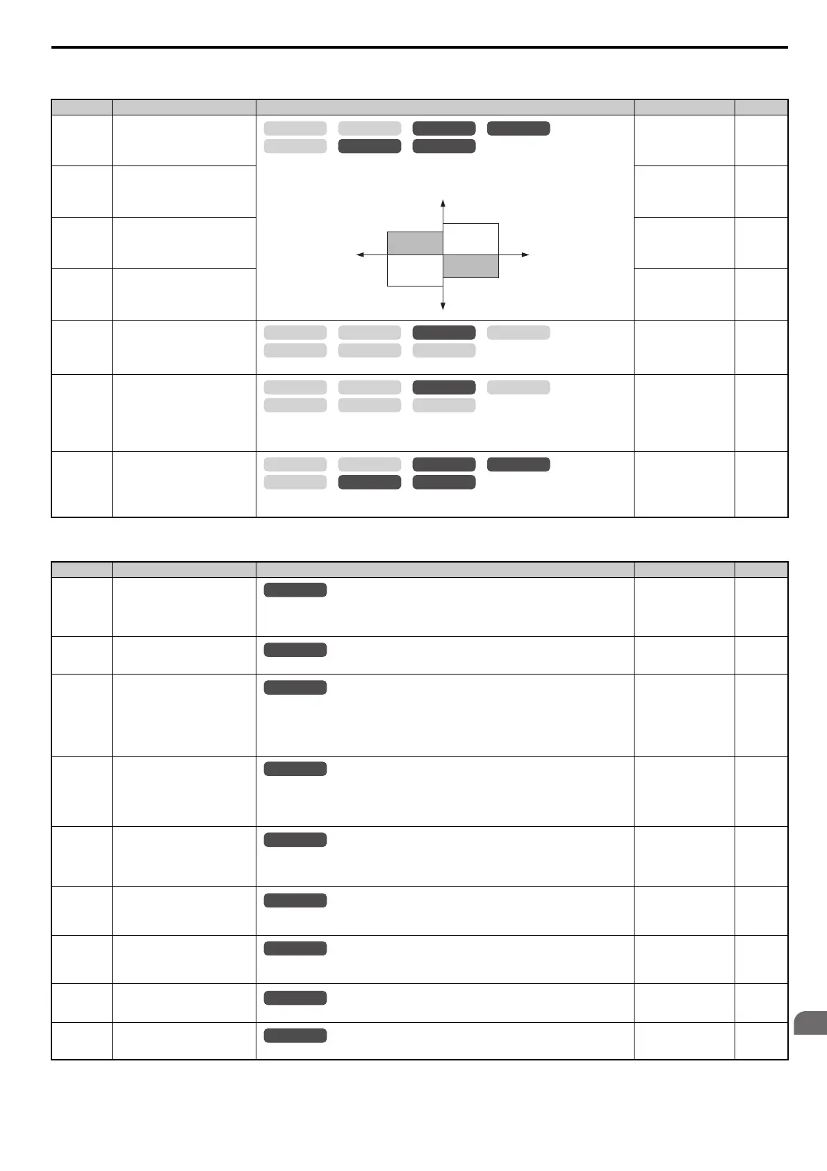
Forward Torque Limit
Sets the torque limit value as a percentage of the motor rated torque. Four individual quadrants
can be set.
Default: 200%
Min: 0%
Max: 300%
294
L7-02
(4A8H)
Reverse Torque Limit
Default: 200%
Min: 0%
Max: 300%
294
L7-03
(4A9H)
Forward Regenerative Torque
Limit
Default: 200%
Min: 0%
Max: 300%
294
L7-04
(4AAH)
Reverse Regenerative Torque
Limit
Default: 200%
Min: 0%
Max: 300%
294
L7-06
(4ACH)
Torque Limit Integral Time
Constant
Sets the integral time constant for the torque limit.
Default: 200 ms
Min: 5 ms
Max: 10000 ms
294
L7-07
(4C9H)
Torque Limit Control Method
Selection during Accel/Decel
0: Proportional control (changes to integral control at constant speed). Use this setting when
acceleration to the desired speed should take precedence over the torque limit.
1: Integral control. Set L7-07 to 1 if the torque limit should take precedence.
Default: 0
Min: 0
Max: 1
295
L7-16
(44DH)
Torque Limit Process at Start
0: Disabled
1: Enabled
Default: 1
Min: 0
Max: 1
295
No. (Addr.) Name Description Setting Page
L8-01
(4ADH)
Internal Dynamic Braking Resistor
Protection Selection (ERF type)
0: Resistor overheat protection disabled
1: Resistor overheat protection enabled
Note: This parameter is not available in models CIMR-A4A0930 and 4A1200.
Default: 0
Min: 0
Max: 1
295
L8-02
(4AEH)
Overheat Alarm Level
An overheat alarm will occur if the heatsink temperature exceeds the level set in L8-02.
Default:
<6>
Min: 50C
Max: 150C
295
L8-03
(4AFH)
Overheat Pre-Alarm Operation
Selection
0: Ramp to stop. A fault is triggered.
1: Coast to stop. A fault is triggered.
2: Fast Stop. Decelerate to stop using the deceleration time in C1-09. A fault is triggered.
3: Continue operation. An alarm is triggered.
4: Continue operation at reduced speed as set in L8-19.
Default: 3
Min: 0
Max: 4
296
L8-05
(4B1H)
Input Phase Loss Protection
Selection
Selects the detection of input current phase loss, power supply voltage imbalance, or main
circuit electrolytic capacitor deterioration.
0: Disabled
1: Enabled
Default: 1
Min: 0
Max: 1
297
L8-07
(4B3H)
Output Phase Loss Protection
Selection
0: Disabled
1: Enabled (triggered by a single phase loss)
2: Enabled (triggered when two phases are lost)
Default: 0
Min: 0
Max: 2
297
L8-09
(4B5H)
Output Ground Fault Detection
Selection
0: Disabled
1: Enabled
Default:
<6>
Min: 0
Max: 1
297
L8-10
(4B6H)
Heatsink Cooling Fan Operation
Selection
0: Run with timer (Fan operates only during run and for L8-11 seconds after stop.)
1: Run always (Cooling fan operates whenever the drive is powered up.)
Default: 0
Min: 0
Max: 1
297
L8-11
(4B7H)
Heatsink Cooling Fan Off Delay
Time
Sets a delay time to shut off the cooling fan after the Run command is removed when L8-10 = 0.
Default: 60 s
Min: 0 s
Max: 300 s
298
L8-12
(4B8H)
Ambient Temperature Setting
Enter the ambient temperature. This value adjusts the oL2 detection level.
Default: 40C
Min: -10C
Max: 50C
298
OLV/PM AOLV/PM
CLV
V/f w/PG
CLV/PM
V/f OLV
L7-01
L7-03
L7-02
L7-04
Output Torque
Positive Torque
REV
Negative Torque
FWD
Motor
min
-1
Regeneration
Regeneration
OLV/PM AOLV/PM
CLV
V/f w/PG
CLV/PM
V/f OLV
OLV/PM AOLV/PM
CLV
V/f w/PG
CLV/PM
V/f OLV
OLV/PM AOLV/PM
CLV
V/f w/PG
CLV/PM
V/f OLV
All Modes
All Modes
All Modes
All Modes
All Modes
All Modes
All Modes
All Modes
 Loading...


