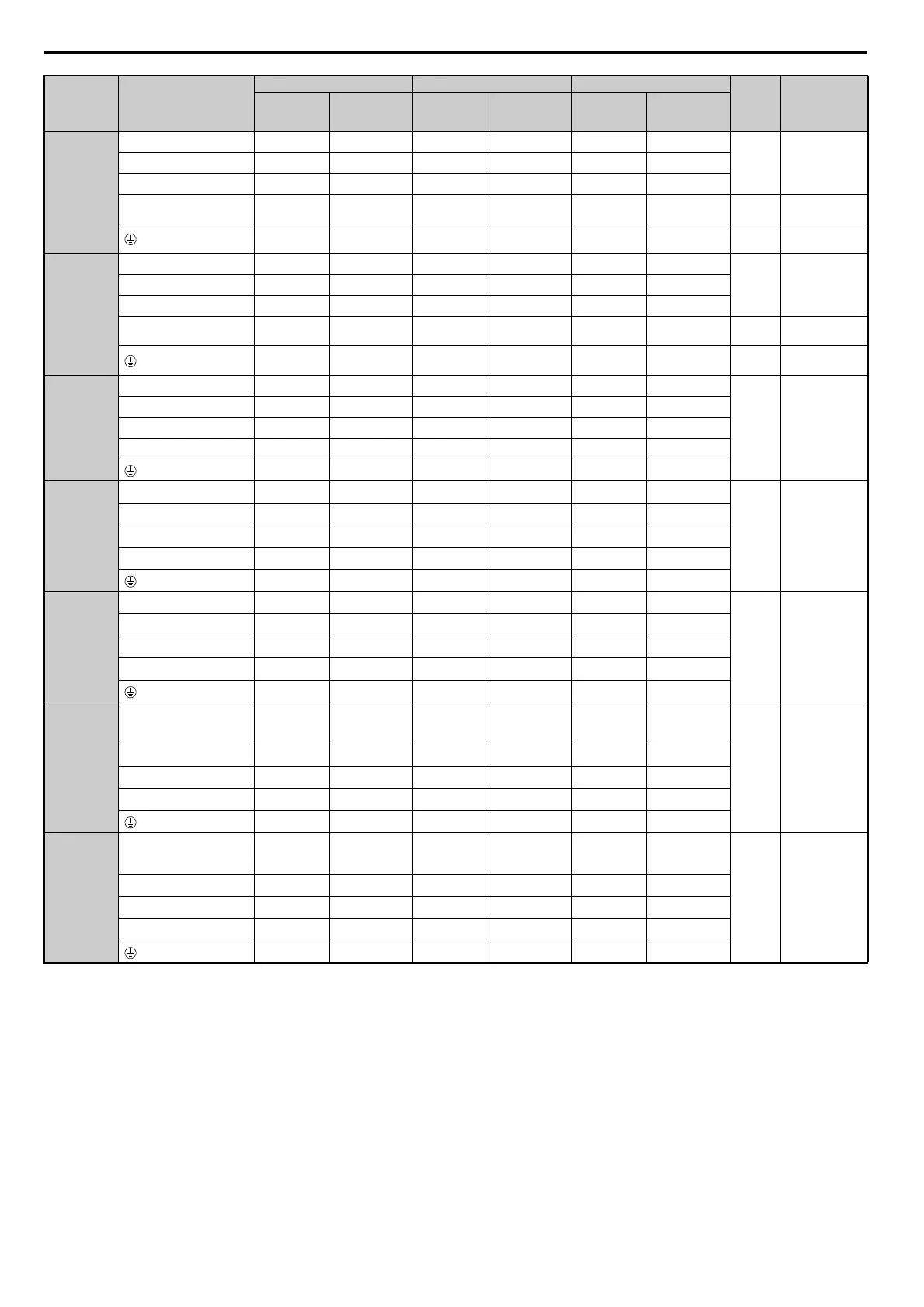
D.3 UL Standards
590 YASKAWA ELECTRIC SIEP C710616 27G YASKAWA AC Drive A1000 Technical Manual
Note: Use crimp insulated terminals or insulated tubing for wiring these connections. Wires should have a continuous maximum
allowable temperature of 75C 600 V UL approved vinyl sheathed insulation. Ambient temperature should not exceed 40C.
4A0296
<4>
R/L1, S/L2, T/L3 185 95 to 300 500 2/0 to 600 200 80 to 325
M12
32 to 40
(283 t
o 354)
U/T1, V/T2, W/T3 185 95 to 300 500 2/0 to 600 200 80 to 325
–, +1 – 70 to 300 – 3/0 to 600 325 80 to 325
+3 – 35 to 300 – 1 to 325 150 38 to 325 M10
18 to 23
(159 t
o 204)
95 95 to 240 2 2 to 350 30 30 to 200 M12
32 to 40
(283 to 354)
4A0362
<4>
R/L1, S/L2, T/L3 240 95 to 300 4/0 2P 3/0 to 600 250 80 to 325
M12
32 to 40
(283 t
o 354)
U/T1, V/T2, W/T3 240 95 to 300 4/0 2P 3/0 to 600 250 80 to 325
–, +1 – 95 to 300 – 4/0 to 600 325 100 to 325
+3 – 70 to 300 – 3/0 to 600 200 80 to 325 M10
18 to 23
(159 t
o 204)
120 120 to 240 1 1 to 350 30 30 to 200 M12
32 to 40
(283 to 354)
4A0414
<4> <5>
R/L1, S/L2, T/L3 95 2P 95 to 150 300 2P 4/0 to 300 100 2P 80 to 150
M12
32 to 40
(283 t
o 354)
U/T1, V/T2, W/T3 95 2P 95 to 150 300 2P 4/0 to 300 125 2P 80 to 150
–, +1 – 70 to 150 – 3/0 to 300 150 2P 80 to 150
+3 – 70 to 150 – 3/0 to 300 80 2P 80 to 150
95 35 to 95 1 1 to 3/0 38 38 to 100
4A0515
<4> <5>
R/L1, S/L2, T/L3 120 2P 95 to 150 3/0 4P 3/0 to 300 125 2P 80 to 150
M12
32 to 40
(283 t
o 354)
U/T1, V/T2, W/T3 150 2P 95 to 150 4/0 4P 3/0 to 300 150 2P 80 to 150
–, +1 – 70 to 150 – 1/0 to 300 60 4P 60 to 150
+3 – 70 to 150 – 1/0 to 300 100 2P 60 to 150
150 50 to 150 1/0 1/0 to 300 60 50 to 150
4A0675
<4> <5>
R/L1, S/L2, T/L3 95 4P 95 to 150 300 4P 4/0 to 300 80 4P 80 to 150
M12
32 to 40
(283 t
o 354)
U/T1, V/T2, W/T3 95 4P 95 to 150 300 4P 4/0 to 300 80 4P 80 to 150
–, +1 – 70 to 150 – 1/0 to 300 125 4P 60 to 150
+3 – 70 to 150 – 1/0 to 300 60 4P 60 to 150
95 2P 60 to 150 2/0 2/0 to 300 60 70 to 150
4A0930
<4> <5>
R/L1, S/L2, T/L3,
R1/L11, S1/L21,
T1/L31
120 4P 95 to 150 (4/0 4P) 2 3/0 to 300 150 4P 125 to 150
M12
32 to 40
(283 t
o 354)
U/T1, V/T2, W/T3 120 4P 95 to 150 (4/0 4P) 2 3/0 to 300 150 4P 125 to 150
–, +1 – 95 to 150 – 4/0 to 300 (125 4P) 2 100 to 150
+3 – 95 to 150 – 4/0 to 300 125 4P 100 to 150
120 2P 70 to 120 3/0 3/0 to 250 100 80 to 125
4A1200
<4> <5>
R/L1, S/L2, T/L3,
R1/L11, S1/L21,
T1/L31
(95 4P) 2 95 to 150 (300 4P) 2 4/0 to 300 (125 4P) 2 100 to 150
M12
32 to 40
(283 t
o 354)
U/T1, V/T2, W/T3 (95 4P) 2 95 to 150 (300 4P) 2 4/0 to 300 (125 4P) 2 100 to 150
–, +1 – 120 to 150 – 250 to 300 (150 4P) 2 125 to 150
+3 – 95 to 150 – 4/0 to 300 (100 4P) 2 100 to 150
95 4P 95 to 120 4/0 4/0 to 250 125 100 to 125
<1> Gauges listed here are for use in Europe and China.
<2> Gauges listed here are for use in the United States.
<3> Gauges listed here are for use in Asia except for China.
<4> Drive models CIMR-A4A0058 to 4A1200 require the use of closed-loop crimp terminals for UL/cUL compliance. Use only the tools
recommended by the terminal manufacturer for crimping.
<5> When an EMC filter is installed, additional measures must be taken in order to comply with IEC/EN 61800-5-1. Refer to EMC Filter
Installation on page 580.
Model
CIMR-A
Terminal
For Europe and China <1> For U.S.A. <2> For Asia <3>
Screw
Size
Tightening
Torque
Nm (lb.in.)
Recomm.
Wire Size
mm
2
Applicable
Gauge
mm
2
Recomm.
Gauge
AWG, kcmil
Applicable
Gauge
AWG, kcmil
Recomm.
Wire Size
mm
2
Applicable
Gauge
mm
2

 Loading...


