5-10
IM DLM6054-01EN
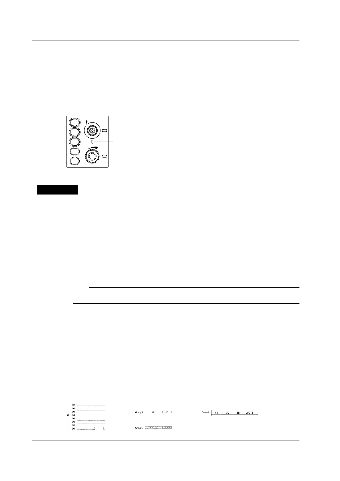
Setting the Vertical Display Range (SCALE)
Press LOGIC to make the SCALE knob control the LOGIC setting.
Turn the SCALE knob to set the vertical display range.
Setting the Vertical Position (POSITION)
Press LOGIC to make the POSITION knob control the LOGIC setting.
Turn the POSITION knob to set the vertical position.
VERTICAL
POSITION
PUSH
0DIV
SCALE
PUSH
FINE
1
2
3
4
LOGIC
Illuminates in the color that represents the LOGIC channel (blue)
Explanation
Hiding the Logic Signal Area (Mode)
When you press the LOGIC key, it illuminates, the screen is divided in two, and a logic signal area
appears below the normal analog signal area.
When you set Mode to OFF, the logic signal area is hidden. The logic signal area is also hidden if you
press LOGIC when the LOGIC key menu is displayed.
Turning Logic Signal Displays On and Off by Group (Select,
Display)
You can turn the display of logic signals on and off by group. To assign logic signals to groups, press
the Mapping soft key.
Note
• Groups that do not have logic signals (bits) assigned to them will not appear.
• Logic signals (bits) that have not been assigned to groups will not appear.
Display Order (Order)
You can specify the order in which the five groups in the logic signal area are displayed.
Bus Display (Bundle)
You can show the logic signals of each group using the bus display. In the bus display, you can display
signals in hexadecimal or binary format or by using symbols. For information about how bits are
handled when you select the hexadecimal format, see “Grouping Settings.”
* Symbols are a way of expressing bit sequences that include “d
on’t cares” (Xs). You can load
physical value/symbol definition files (with .sbl extensions) that you have edited using the Symbol
Editor tool.
• Hexadecimal display (Hex) • Symbol display (Sym)
• Binary display (Bin)
When the Bus Display is Off When the Bus Display is On
5.2 Vertical Axis Settings for Logic Input Signals
 Loading...


