5-19
IM 701450-01E
5
Vertical and Horizontal Axes
Explanation
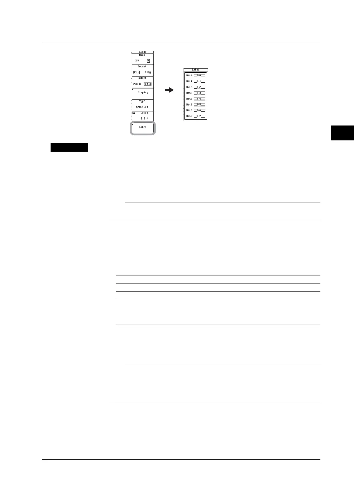
Each bit of the optional logic input can be turned ON/OFF, and the threshold level can be
specified.
Turning ON/OFF the Logic Input
If you turn ON the logic input, a logic waveform display frame opens.
Note
To display the logic waveform display frame on a full screen, press the Format soft key and
select Only (see section 8.1).
Selecting the Bits to Be Displayed
You can specify the bits to be displayed on each pod. If all the bits of either POD A or
POD B are turned OFF, the vertical display range of the other pod is expanded.
Threshold Level
You can select the threshold level of the input signal for each pod.
CMOS(5V) 2.5 V
CMOS(3.3V) 1.6 V
ECL –1.3 V
User User-defined setting
Selectable range: ±40 V when using the 701980 Logic Probe, ±10 V
when using the 701981 Logic Probe
Resolution: 0.1 V
Assigning the Waveform Labels
You can set a waveform label for each bit using up to 8 characters.
Note
• If the acquisition mode is set to Average or Box Average while using the logic input, average
or box average applies only to analog waveforms.
• If interleave mode is turned ON, Pod B cannot be used.
• The threshold level for the external clock input and the trigger level for the external trigger
input are common.
5.10 Turning ON/OFF the Logic Input and Setting the Threshold Level

 Loading...


