6-32 IM 701450-01E
Explanation
This setting is for activating a trigger on the OR logic of the edge trigger or the OR logic
of the window trigger of each channel.
Slope of the Edge Trigger of Each Channel
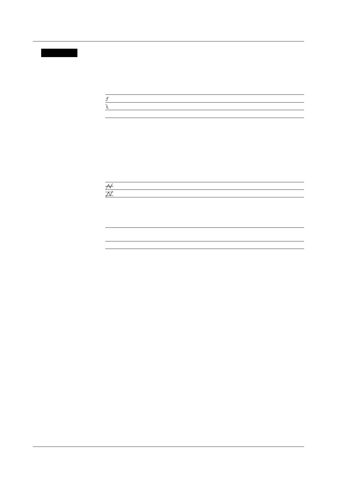
You can select the slope of the edge trigger of each channel.
Rising slope
Falling slope
– Don’t Care
Trigger Level
The selectable range is 8 divisions within the screen. The resolution is 0.01 divisions.
For example, the resolution for 2 mV/div is 0.02 mV.
Hysteresis
Sets a width to the trigger level so that triggers are not activated by small changes in the
trigger signal.
Approximately 0.3 divisions
*
of hysteresis around the trigger level.
Approximately 1 division
*
of hysteresis around the trigger level.
* The value above is an approximate value. It is not strictly warranted.
Trigger Coupling
You can select the trigger coupling.
AC Uses a signal that is obtained by removing the DC component from the trigger source
signal.
DC Uses the trigger source signal as-is.
Turning ON/OFF the HF Rejection
Specify 15 kHz or 20 MHz if you wish to use a signal that is obtained by removing the
high frequency components (frequency components greater than 15 kHz or 20 MHz)
from the trigger source signal as the trigger source.
Relationship with the Window
When Window is turned ON, a trigger is activated on the OR logic of the window
conditions. For details on the window, see section 6.13.
Hold Off
See section 6.4.
6.12 Setting the OR Trigger (ENHANCED)

 Loading...


