2-3
IM 701450-01E
2
Explanation of Functions
Input Coupling <For the setup procedure, see section 5.4>
If you wish to observe just the amplitude of an AC signal, it is best to remove the DC
component from the input signal. On the other hand, there are times when you wish to
check the ground level or observe the entire input signal (both the DC and AC
components). In these cases, you can change the input coupling setting. By changing
the input coupling, the method used to input the signal to the vertical control circuit
(voltage axis) is switched. The following types of input coupling are available.
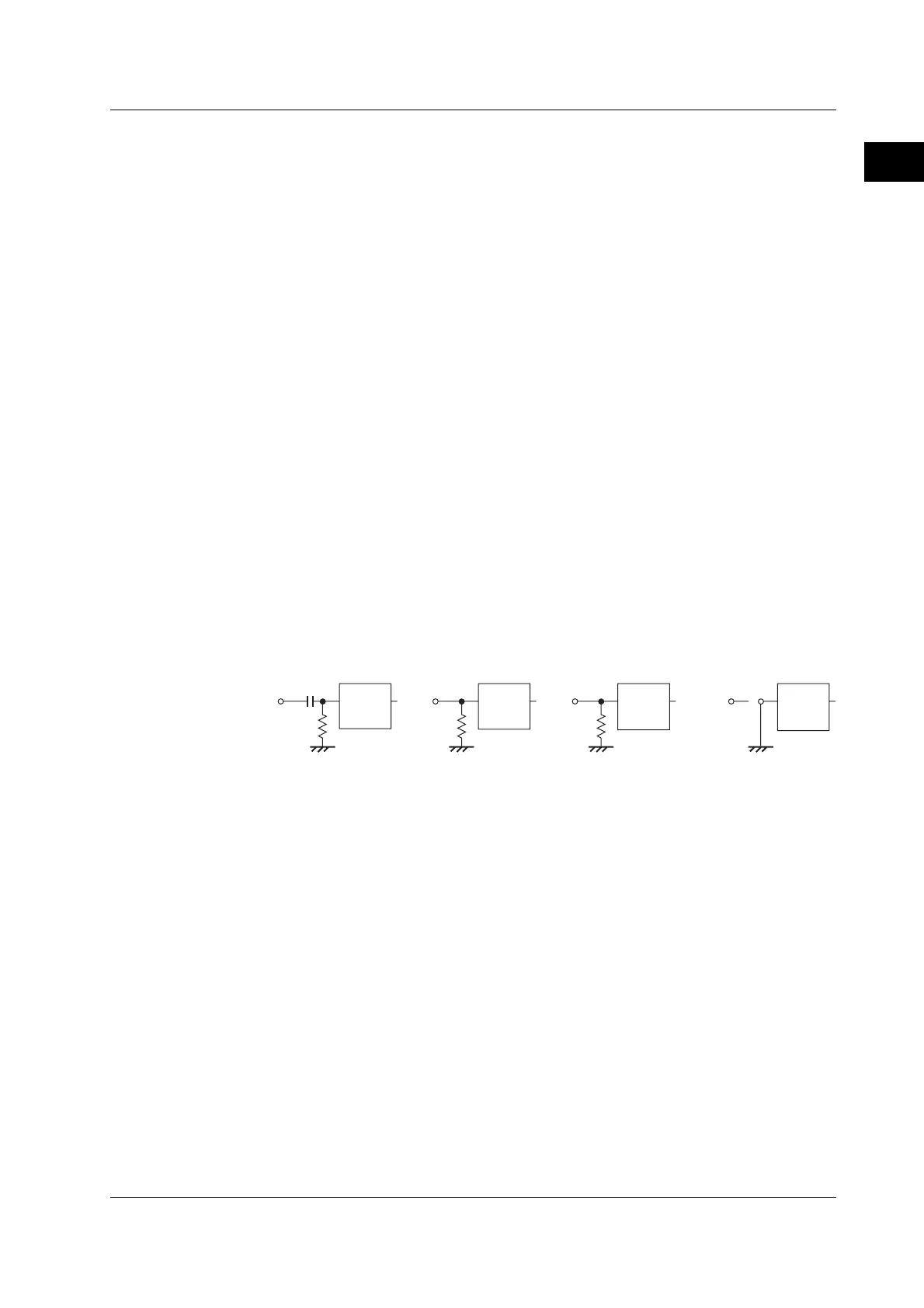
AC1MΩ
The input signal is coupled to the attenuator of the vertical control circuit through a
capacitor. This setting is used when you wish to observe only the amplitude of the AC
signal, eliminating the DC component from the input signal.
DC1MΩ
The input signal is directly coupled to the attenuator of the vertical control circuit. Use
this setting if you wish to observe the entire input signal (DC component and AC
component).
DC50Ω
This setting is similar to DC1MΩ described above except the input impedance is 50 Ω.
Use caution because the maximum input voltage is decreased.
GND
The input signal is coupled to the ground, not to the attenuator of the vertical control
circuit. You can use this setting to check the ground level on the screen.
Vertical
control
circuit
1MΩ
Vertical
control
circuit
DC1MΩ
Vertical
control
circuit
50Ω
DC50Ω
Vertical
control
circuit
Input
terminal
Input
terminal
Input
terminal
Input
terminal
1MΩ
AC1MΩ GND
Probe Attenuation/Current-to-Voltage Conversion Ratio <For the setup procedure, see
section 5.5>
Normally a probe is used in connecting the circuit being measured to the measurement
input terminal. Using a probe has the following advantages.
• Avoids disturbing the voltage and current of the circuit being measured.
• Inputs the signal with no distortion.
• Expands the voltage range that the DL7400 can measure.
The DL7400 comes standard with 400 MHz passive probes. The probe attenuates the
voltage signal to 1/10. When using a probe, the attenuation setting on the DL7400 must
be set equal to the probe attenuation so that the measured voltage can be read directly.
When using the 400-MHz passive probes (voltage probes) that came with the package,
set the probe attenuation to 10:1. The DL7400 has voltage probe settings of 10:1, 1:1,
100:1, and 1000:1 and current probe settings of 10 A:1 V and 100 A:1 V. If you are
using a probe other than the ones that came with the package, set the attenuation ratio
on the DL7400 according to the attenuation of the probe.
2.2 Vertical and Horizontal Axes

 Loading...


