2-4 IM 701450-01E
Offset Voltage <For the setup procedure, see section 5.6>
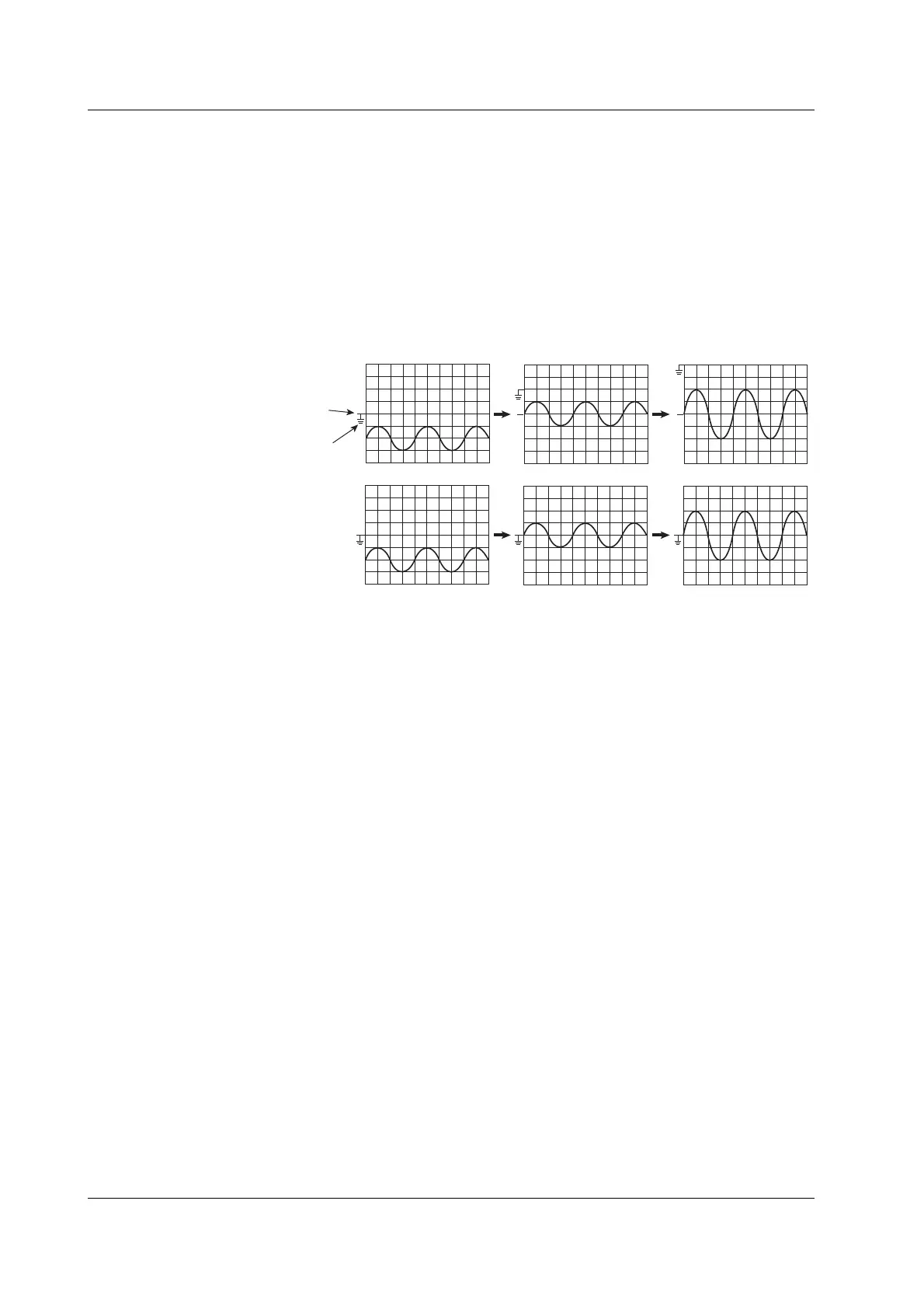
When observing a voltage riding on top of a predetermined voltage, an offset voltage can
be applied to eliminate the predetermined voltage so that only the changes in the signal
can be observed with higher vertical axis sensitivity. Usually, the offset voltage does not
affect the cursor measurement values, the result of the automated measurement of
waveform parameters, or the computed values. However, you can apply the offset
voltage to cursor measurement values, the result of the automated measurement of
waveform parameters, and the computed values by setting Offset Cancel to ON (see
section 15.3).
1.00 V/div
Offset 0.00 V
Position 0.00 div
1.00 V/div
Offset –2.00 V
Position 0.00 div
0.500 V/div
Offset –2.00 V
Position 0.00 div
When Offset
Cancel is OFF
When Offset
Cancel is ON
Vertical
position
mark
GND level
mark
Bandwidth Limit <For the setup procedure, see section 5.8>
You can set a bandwidth limit at 20 MHz or 100 MHz against the input signal for each
channel. You can observe waveforms with the noise components above the specified
frequency eliminated.
Linear Scaling <For the setup procedure, see section 5.9>
When observing voltages or currents, you can change the vertical axis scale values of
the displayed waveforms (see page 2-20) to scaled values. By setting scaling coefficient
A, offset value B, and a unit, you can multiply the division ratio of an external voltage
divider or convert the voltage measurement to current values. Linear scaling also
applies to the measured values of cursor measurements and automated measurement of
waveform parameters.
Y (UNIT) = AX + B
X: Value before scaling
Y: Value after scaling
Logic Signal Input (Optional) <For the setup procedure, see section 5.10>
You can observe logic signals by connecting a logic probe to the logic probe input
connector on the rear panel. Two logic input ports, Pod A and Pod B, are available.
Each pod can receive 8 bits.
2.2 Vertical and Horizontal Axes

 Loading...


