2-5
IM 701450-01E
2
Explanation of Functions
Horizontal Axis (Time Axis)
Selecting the Time Base <For the setup procedure, see section 5.11>
By default, the sampling timing of the measured waveform is controlled by the internal clock
signal generated from the time base circuit within the DL7400 (see the block diagram in
section 1.1). The timing can also be controlled by a clock signal applied externally.
External clock signals are input through the external clock input terminal on the rear
panel. The external clock input is useful for observing a signal whose period varies or for
observing waveforms by synchronizing to the clock signal of the signal being measured.
Time Axis Setting <For the setup procedure, see section 5.12>
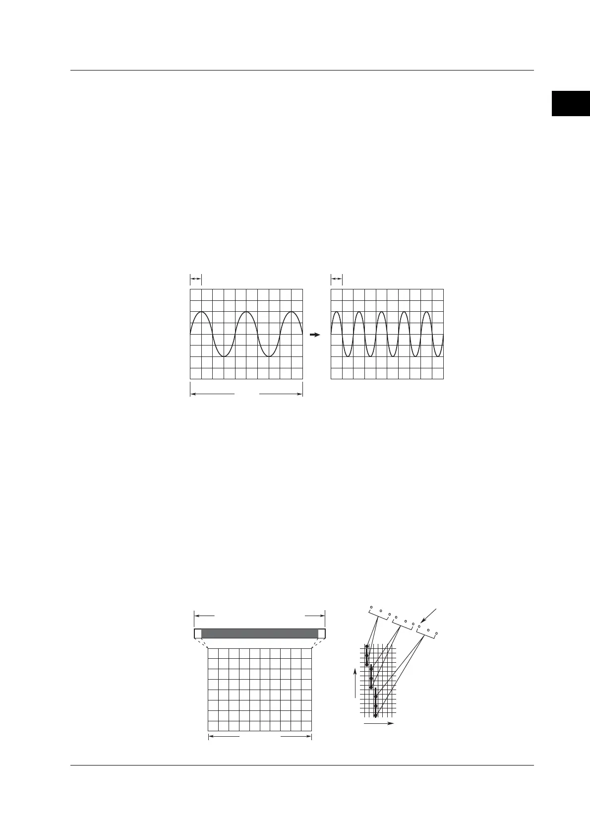
When using the internal clock, the time axis scale (T/div) is set in terms of the time per
one grid square (1 division). The selectable range is 1 ns/div to 50 s/div (1 ns/div to 5 s/
div when the record length is 1 k.) Since the display span along the horizontal axis is 10
divisions, the time span of the displayed waveform is equal to “T/div×10.”
1 div = 500 µs
10 div
1 div = 1 ms
Display along the Time Axis
Sampled data of the length equal to the specified record length is acquired to the
acquisition memory, and waveforms are displayed based on the stored data. The
number of display lines in 10 divisions of the screen (along the time axis) is 500 (250
lines in the zoom waveform display section of Main & Z1 & Z2). Therefore, the
waveforms are processed according to the display record length (see page 2-15) as
described below. For more details about the relationship between the time axis,
acquisition mode, record length of the acquisition memory (specified record length),
display record length, and other parameters, see appendix 1.
• When the display record length is greater than the number of displayed points
The multiple data points existing on the same display line on the time axis are
connected by a line and displayed.
• When the display record length is less than the number of displayed points
Display interpolation is performed (see section 2.4).
500 lines
Sampled data
Time axis
Voltage axis
Display record length
Record length of the
acquisition memory
(Specified record length)
On the screen
2.2 Vertical and Horizontal Axes

 Loading...


