10-52 IM 701450-01E
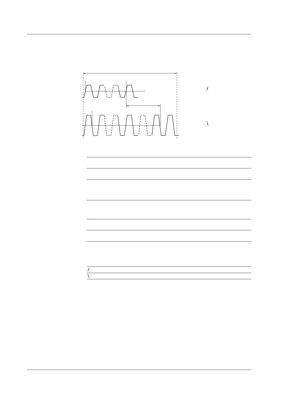
Delay between Waveforms
The time difference between the rising or falling edge between waveforms and the time
difference from the trigger point to the rising or falling edge of waveforms can be
measured.
(Rising)
N1 (integer between 1 and 9)
(Falling)
N2 (integer between 1 and 9)
Reference
waveform
Measured
waveform
1st time
N1th time
N2th time
1st time
Delay between
waveforms
• Polarity:
• Edge Count:
Reference waveform setup example
Measured waveform setup example
Measurement range
• Polarity:
• Edge Count:
Mesial line
Measurement Mode
You can select the measurement mode.
OFF
Delay between waveforms is not measured.
Time
Displays the delay between waveforms using time.
Degree
Displays the delay between waveforms using angles.
Converting equationAngle = Delay (s)/Period (s) × 360 (deg). The period is that of a
reference waveform.
Reference Point
You can select the reference point used when measuring the delay between waveforms.
Trace
The reference point is set to the edge of the reference waveform.
Trig
The reference point is set to the trigger position.
Slope
You can select which slope, rising or falling, of the waveform to be measured or
reference waveform is to be detected.
Rising slope
Falling slope
Detection Count
Set which edge (count) is to be the reference point or measurement point. The
selectable range is an integer from 1 to 9.
• The level at the detection point is the mesial point.
• The measurement parameter name when displaying the measured value is Dly.
1 Cycle Mode
This mode is used determine the waveform cycle and calculate measurement values
related to the vertical axis or area within the cycle. This mode is suited to measurement
parameters such as Rms and Avg that produce errors depending on the measurement
range. This mode does not affect the measurement parameters related to the time axis
or the area of the X-Y waveforms.
10.6 Automated Measurement of Waveform Parameters
 Loading...


