2-13
IM 701450-01E
2
Explanation of Functions
Single (N) Mode
Waveforms are acquired and stored in different memory areas each time a trigger is
activated the specified number of times. Then, acquisition is stopped, and all the
acquired waveforms are displayed. For details on the acquisition method of waveforms
in Single (N) mode, see “Sequential Store” on page 2-17.
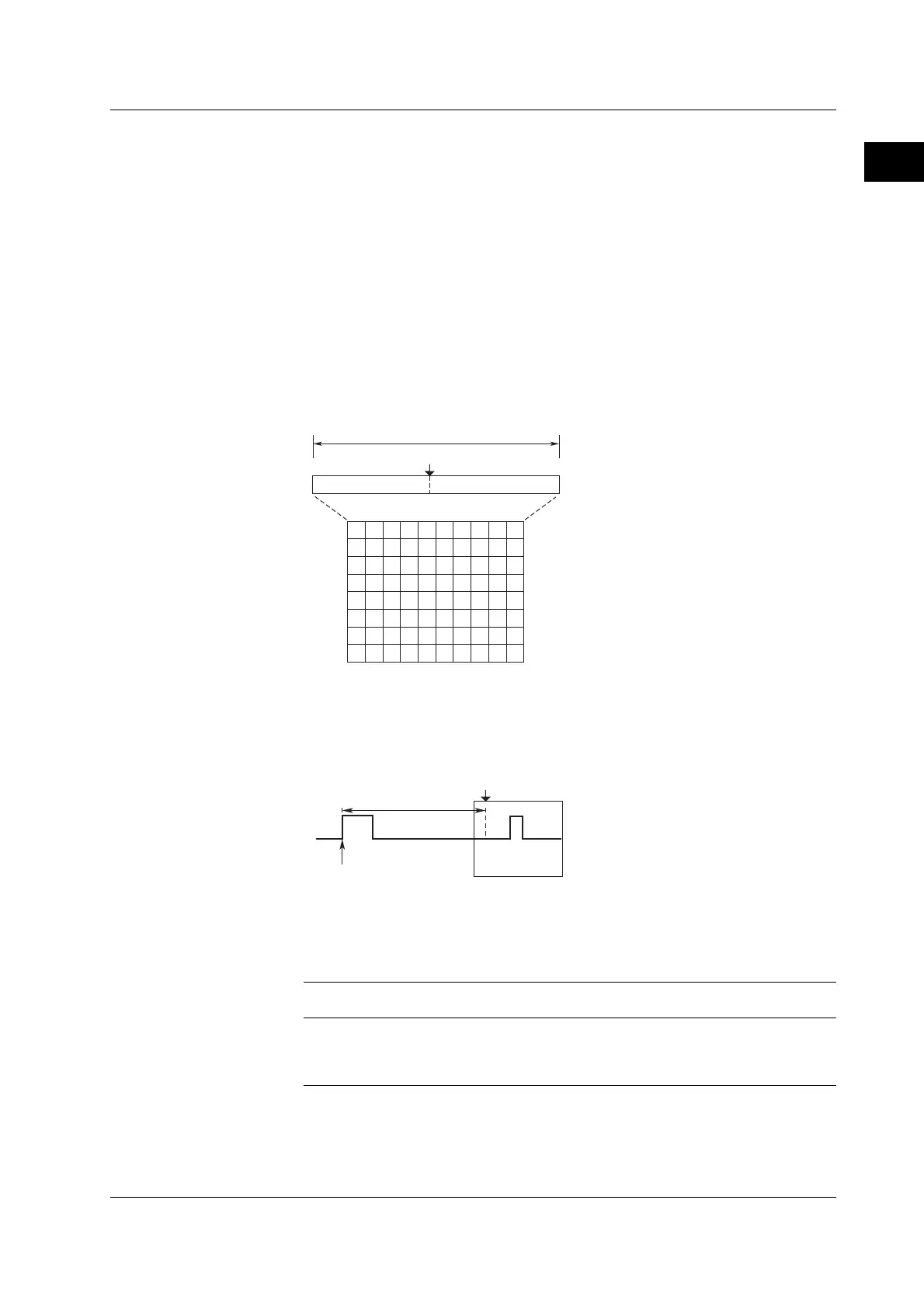
Trigger Position <For the setup procedure, see section 6.2>
When you start waveform acquisition, a trigger is activated according to a specified
trigger condition, and the waveform acquired to the acquisition memory is displayed. If
the trigger delay described below is set to 0 s, the point at which the trigger is activated
(trigger point) and the trigger position match. By moving the trigger position on the
screen, you can change the display ratio of the pre-data—the waveform data stored in
the acquisition memory before the trigger point (pre-trigger section)—and the post-
data—data after the trigger point (post-trigger section).
Display record length
Trigger position
Pre-trigger section
Post-trigger section
0%
100%
Trigger Delay <For the setup procedure, see section 6.3>
Normally, the waveform around the trigger point is displayed. However, by setting a
trigger delay, you can display the waveform that is acquired a specified time after the
trigger point. The selectable range of trigger delay is 0 to 4 s.
Delay
Trigger point
T (Trigger position)
Trigger Coupling <For the setup procedure, see sections 6.5, 6.8 to 6.12>
As with the input signals, the input coupling can be switched on trigger sources. Select
the input coupling that is suitable for the trigger source signal. The following two types of
input coupling are available for the trigger source signal.
DC
Select this setting when using the source as is with no processing of the signal.
AC
Select this setting when using the signal with the DC components removed for the trigger
source. When this setting is used, a trigger can always be activated on signals whose
amplitude is around 1 division or greater if the trigger level is set to 0 V.
2.3 Trigger
 Loading...


