2-12 IM 701450-01E
Logic Trigger <For the setup procedure, see section 6.15>
The DL7400 has two logic probe input connectors, A and B. Each pod can receive 8 bits
of logic signals. A trigger is activated on the rising or falling edge of the clock bit while
the condition consisting of the combination of H, L, and Don’t Care of Pod A and B (16
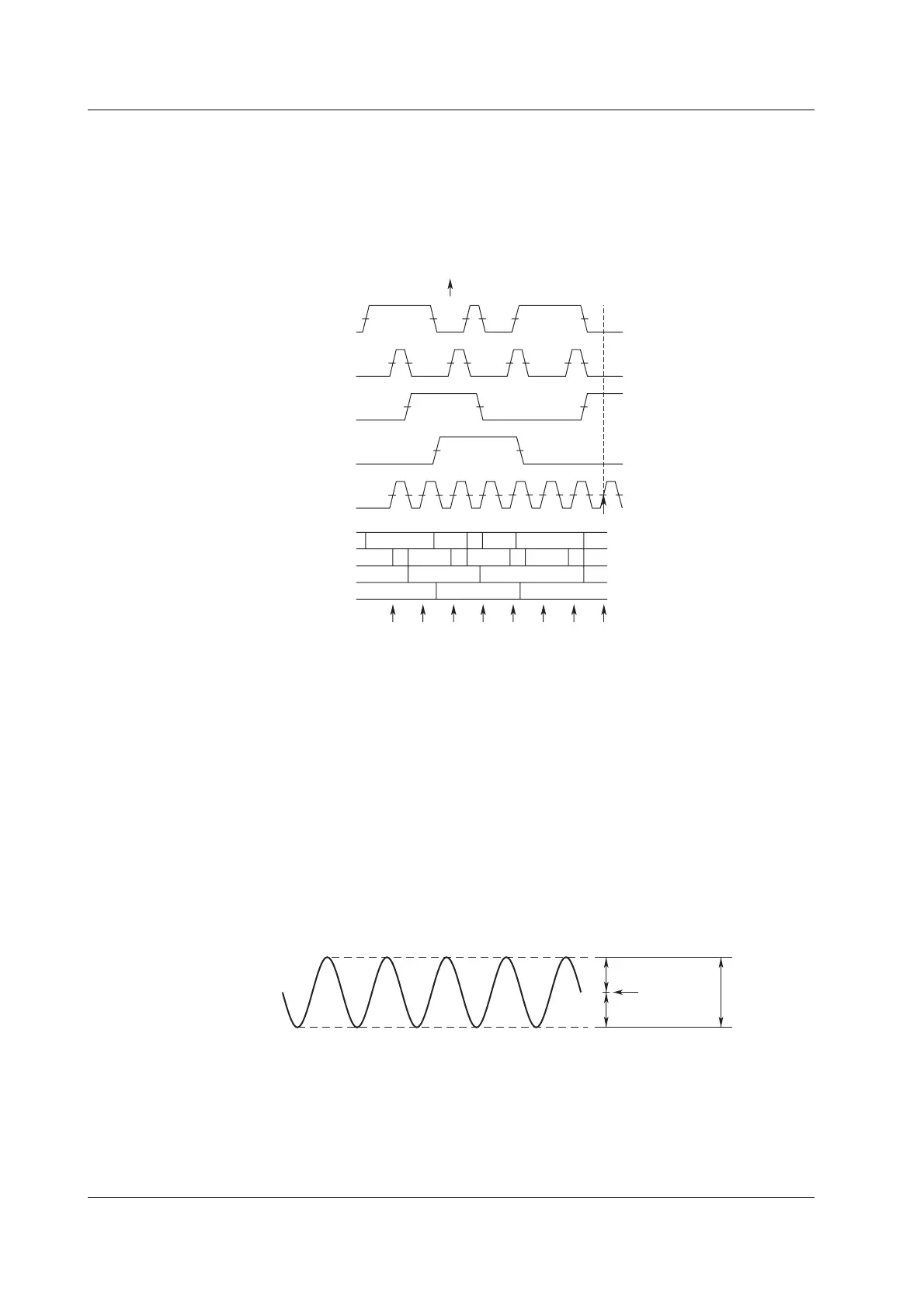
bits) is met. If the clock bit is not specified, a trigger is activated on whether the condition
consisting of the combination of the logic input is met or not met.
LH L L L
H
HHHHLLLL
L
HLLH
HLL
H
Pod A Bit0
Pod A Bit1
Pod A Bit2
Pod A Bit3
Pod A Bit0
Pod A Bit1
Pod A Bit2
Pod A Bit3
Condition
Pod A Bit0
= L,
Pod A Bit1
= L,
Pod A Bit2
= H,
Pod A Bit3
= L,
True, Rising edge of
Clock Bit
A4 (PodA Bit4)
Trigger
Clock bit
Pod A Bit4
Clock Bit
Trigger Mode <For the setup procedure, see section 6.1>
Sets the conditions for updating the displayed waveforms. The following five trigger
modes are available.
Auto Mode
If a trigger occurs within a specified amount of time (approximately 100 ms, referred to
as the
timeout time
), the displayed waveforms are updated. If a trigger is not activated
within the timeout time, the displayed waveforms are automatically updated.
Auto Level Mode
If a trigger occurs within the timeout time, the waveform is displayed in the same fashion
as in auto mode. If a trigger is not activated within the timeout time, then the center
value of the amplitude of the trigger source is detected, and the trigger level is changed
to that value. A trigger is activated using the new value, and the displayed waveforms
are updated.
1/2 the amplitude
1/2 the amplitude
Trigger level Amplitude
Normal Mode
The displayed waveforms are updated only when a trigger occurs. The displayed
waveforms are not updated if a trigger does not occur.
Single Mode
When a trigger is activated, displayed waveforms are updated only once, then
acquisition stops. This mode is useful when you are observing a single-shot signal.
2.3 Trigger

 Loading...


