28 Oct
1997 21:57
CELL-DYN
®
3/35 Sample Loader TS Guide 9140234B-June 1997
VERIFICATION PROCEDURES
VP - 6.4 Mixing Contact Sensor Check/Adjustment
3 - 93
3
Search
Book TOC
Go Back
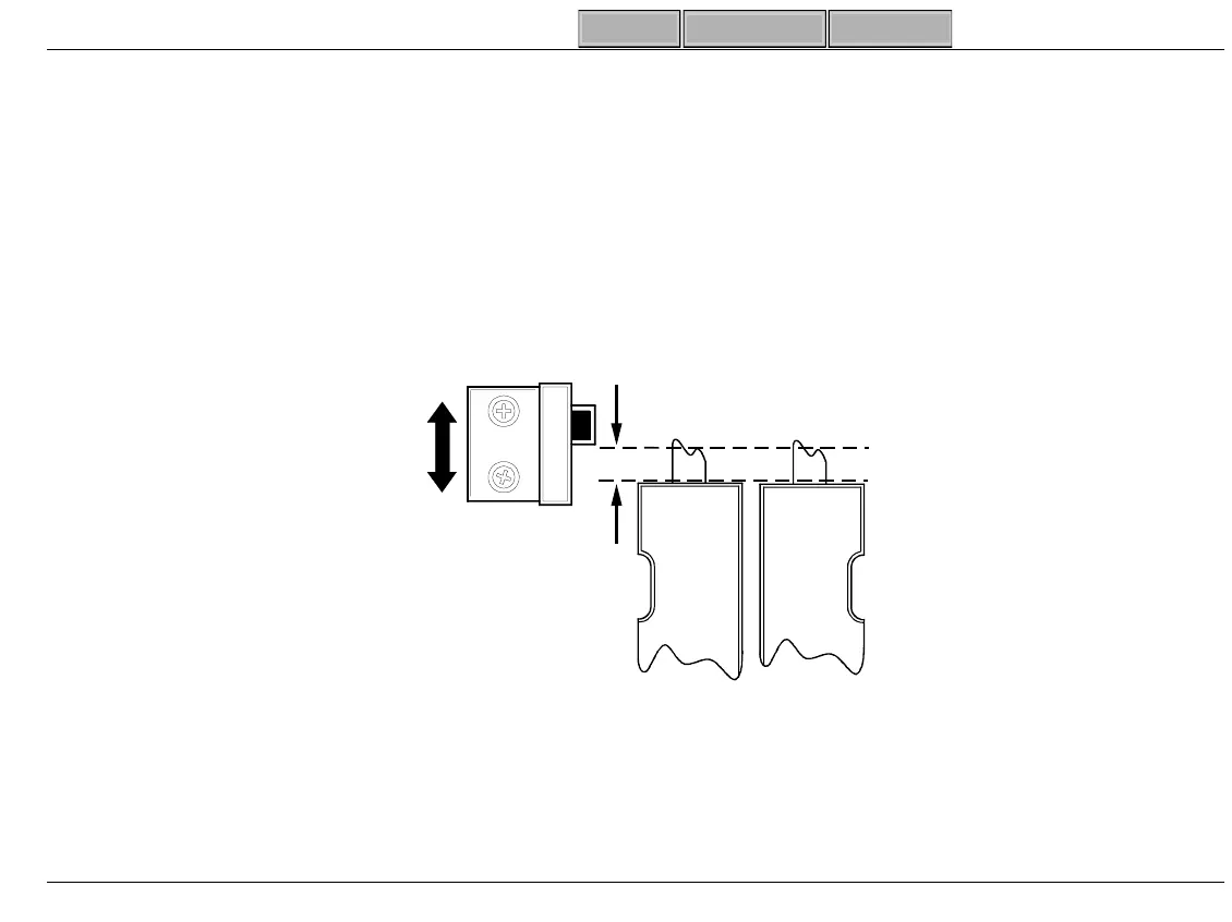
5. Verify Contact Sensor Board Position.
E and F Loaders
[CE MARK]
Top of Mixin
Paddle must be .040-.060 in. (1-1.5 mm) below bottom of Sensor
when Mixin
Head is in Home Position (Z
↑
). See Fi
ure 3-46 and Fi
ure 3-47, Pa
e-3-94.
Figure 3-46
[NON-CE MARK] E Loader
- Top of Mixin
Paddle must be flush with bottom of Sensor
(when Mixin
Assembly is home, Fi
ure 3-48, Pa
e-3-95).
.040 - .060 in
(1.0 - 1.5 mm)
[CE MARK]
SL-269
E- Loader
 Loading...