6241A/6242 DC Voltage Current Source/Monitor Operation Manual
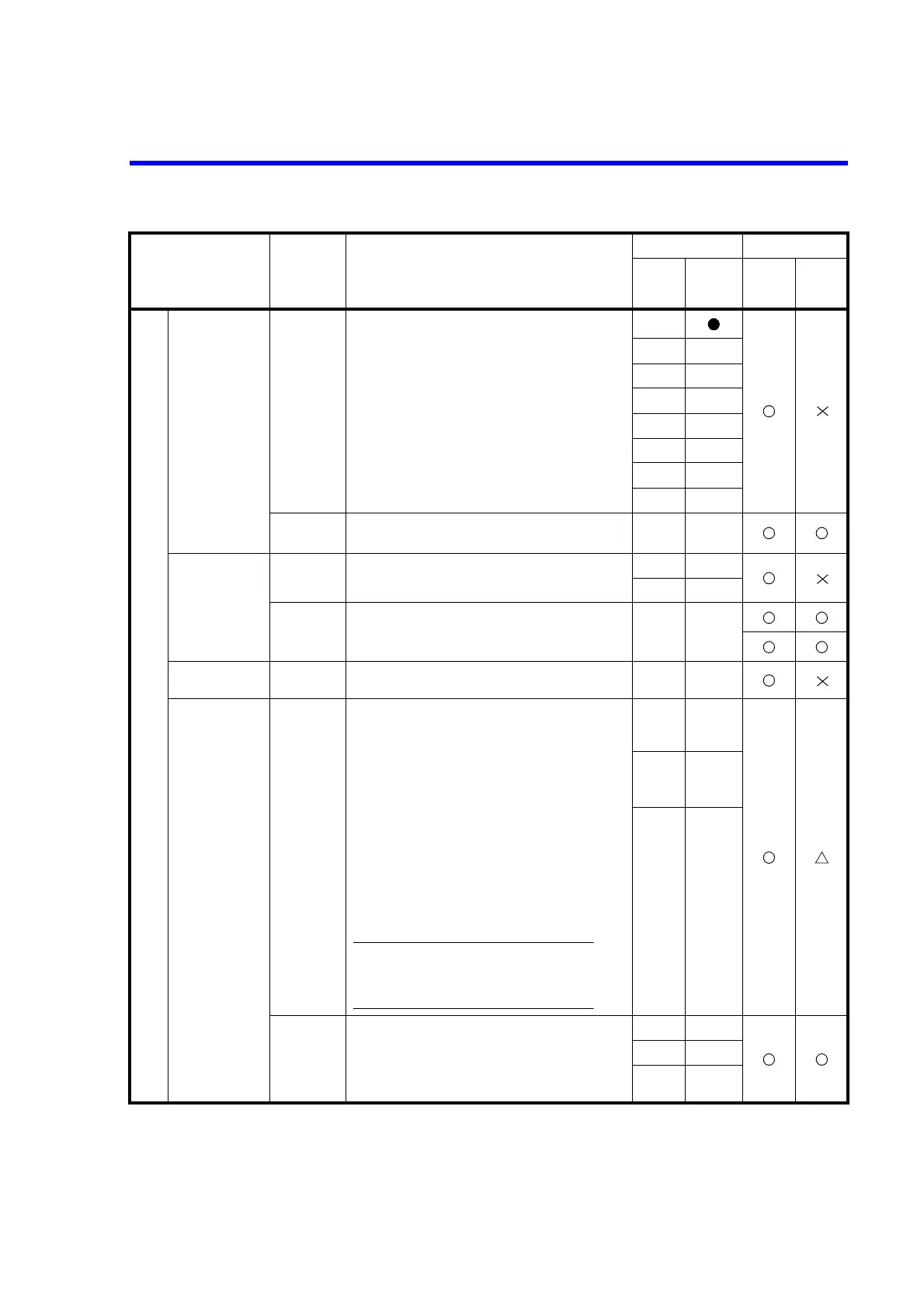
6.7.3 Remote Command List
6-25
Source
Source range SIRX Optimal range
SIR-1 30 µA range
SIR0 300 µA range
SIR1 3 mA range
SIR2 30 mA range
SIR3 300 mA range
SIR4 500 mA/3 A range
SIR5 5 A range
*9
SIR?
Response: SIRX-1
to SIRX 5 (fixed range)
SIR-1 to SIR 5 (fixed range)
Source value SOV ±data Sets voltage source value.
0
SOI ±data Sets current source value.
0
SOV? Response: SOV ± d.ddddE ± d
*1, *2
SOI? SOI ± d.ddddE ± d
Spot command G ±data Executes the measurement trigger after setting the
source value for the currently set source function.
Limiter value LMV
±data1
[,±data2]
Sets voltage limiter value.
±32 V/
±6 V
LMI
±data1
[,±data2]
Sets current-limiter value.
±500
mA/
±300 mA
Both High and Low values can be set for the limiter
values.
* When comparing data1 and data2, the larger value is
High limiter value and the smaller is Low limiter
value.
* data2 can be omitted. In this case, +data1 and -data1
are assumed as High limit and Low limit, regardless
of the data1 polarity.
LMV? Response: LMV ± <hl>, ± <ll>
*1
LMI? LMI ± <hl>, ± <ll>
*1
hl: <d.dddE ± d> (High limiter value)
ll: <d.dddE ± d> (Low limiter value)
*1
*1: The response decimal point is different depending on the set value.
For the source value, limit value, and time parameter set up range, refer to the performance specifications.
*2: Outputs the value that is currently generated or the value that is generated at operation.
*9: An error occurs in 6241A.
Item Command Description
Default Operation
Power
ON
Default
setting
During DC/
pulse
operation and
suspension
During
sweep
operation and
suspension
Note:
1. LMI data1 and data2 can not be set at the same
polarity.
2. Set the difference of High limiter value and Low
limiter value as 60 digits or over.
 Loading...