749
S:\Hp8960\E1962B CDMA 2000\Pi Release\Reference Guide\Chapters\cdma2000_gen_block_diagram.fm
Block Diagram
Block Diagram
Description
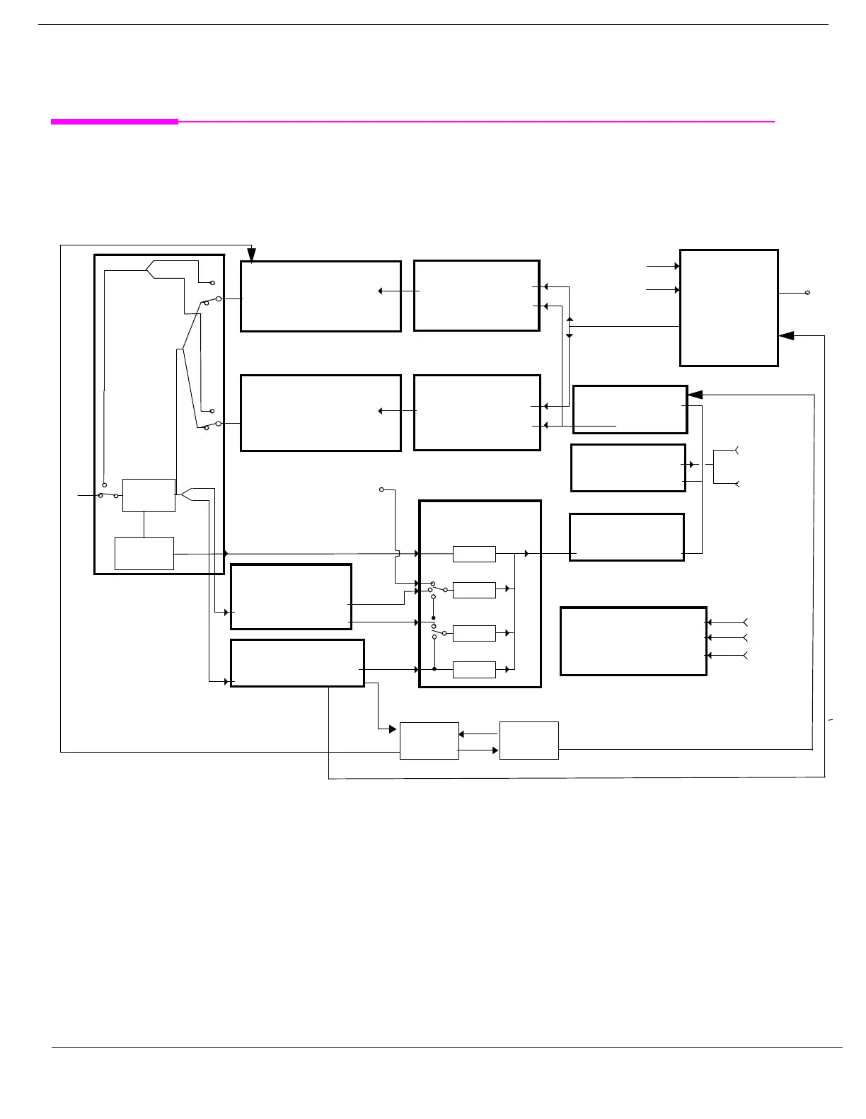
RF Interface Module
Input and output signals are routed through the RF Interface module. The RF Interface module consists of a
directional bridge for sampling incoming power and hybrid power splitters which create 4 bidirectional ports,
(two receiver ports and two source ports), RF amplifiers, video gain circuits, and fast and slow power detectors.
The source signals can be looped back through the input switch to cross calibrate the Measurement
Downconverter and the Power Detector. The directional bridge couples power to the Power Detector.
GPIB
LAN
DVM Lo
DVM Hi
Counter
Analog Digital
Converter
Measurement
Downconverter
Demodulation
Downconverter
RF Source 2
Voltmeter/Counter
Audio Section
Protocol
Processor
Baseband
Generator
Host
Processor
Digital Signal
Processor
RF Source 1
A/D
IF 1
Baseband
Generator
A/D
VME
Bus
A/D
Power
Detector
Log
IF
A/D
(Optional)
(Optional)
Demodulated FM
Bridge
RF
IN
Out
Loop
Back
Link SS
Analog
Link SS
Digital
IF 2
I and Q
PCI Bus
RFIO
AA
AUDIO IN High
AUDIO IN Low
AA

 Loading...


