Ref ID : ADR233B/IM/CS
Rev No. : 05
ADR233B
The MODBUS interface uses ‘TCP’ mode communication rather than ‘ASCII’ mode as this
provides more efficient use of the communication bandwidth. This mode of communication is
defined by the MODBUS standard.
The IED address and baud rate can be selected using the front panel menu or ASHIDA Relay
Talk RTV2 Software.
When using a serial interface, the data format is: 1 starts bit, 8 data bits, 1 stop bit and 1 parity
bit.
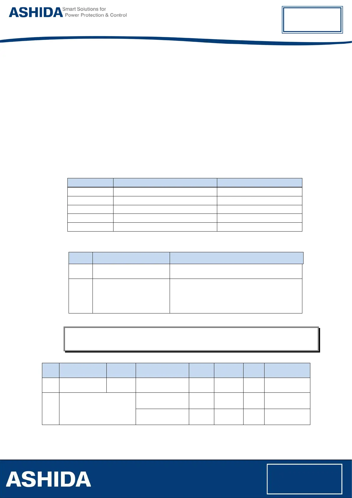
7.2.1 MODBUS Protocol Map
Function Codes supported:
Code Function Name Addresses starts with
Exception Codes generated in case of an error:
Code MODBUS Response Name Product interpretation
01 Illegal Function Code
The function code received in query is not supported
by the IED.
02 Illegal Data Address
The start address r
eceived in the query is not an
allowable value.
NOTE: If the start address received is correct but the
range includes unsupported address this error is
produced.
NOTE: The addresses of the MODBUS registers start from 1 and the user may have to subtract 1 from
the addresses, depending upon the configuration of the Master station configuration.
Sr.
No.
Function
Code
Register
No. of
Regs
Format
Reg.
Type
Address Map
1
Product
Information
03
Manufacturer
Name
10
20-Bytes
ASCII
R 40001 – 40010
Relay Name 10
20-Bytes
ASCII
R 40011 – 40020
02 Read Input Status 1x addresses
03 Read Holding Registers 4x addresses
04 Read Input Registers 3x addresses
05 Force Single Coil 0x addresses
16 Preset Multiple Registers 4x addresses