Parameter descriptions
The analog input signal is mapped to a reference frequency or percentage.
The analog input signal is mapped to a reference frequency or percentage.
Voltage 0…10 V
Parameter
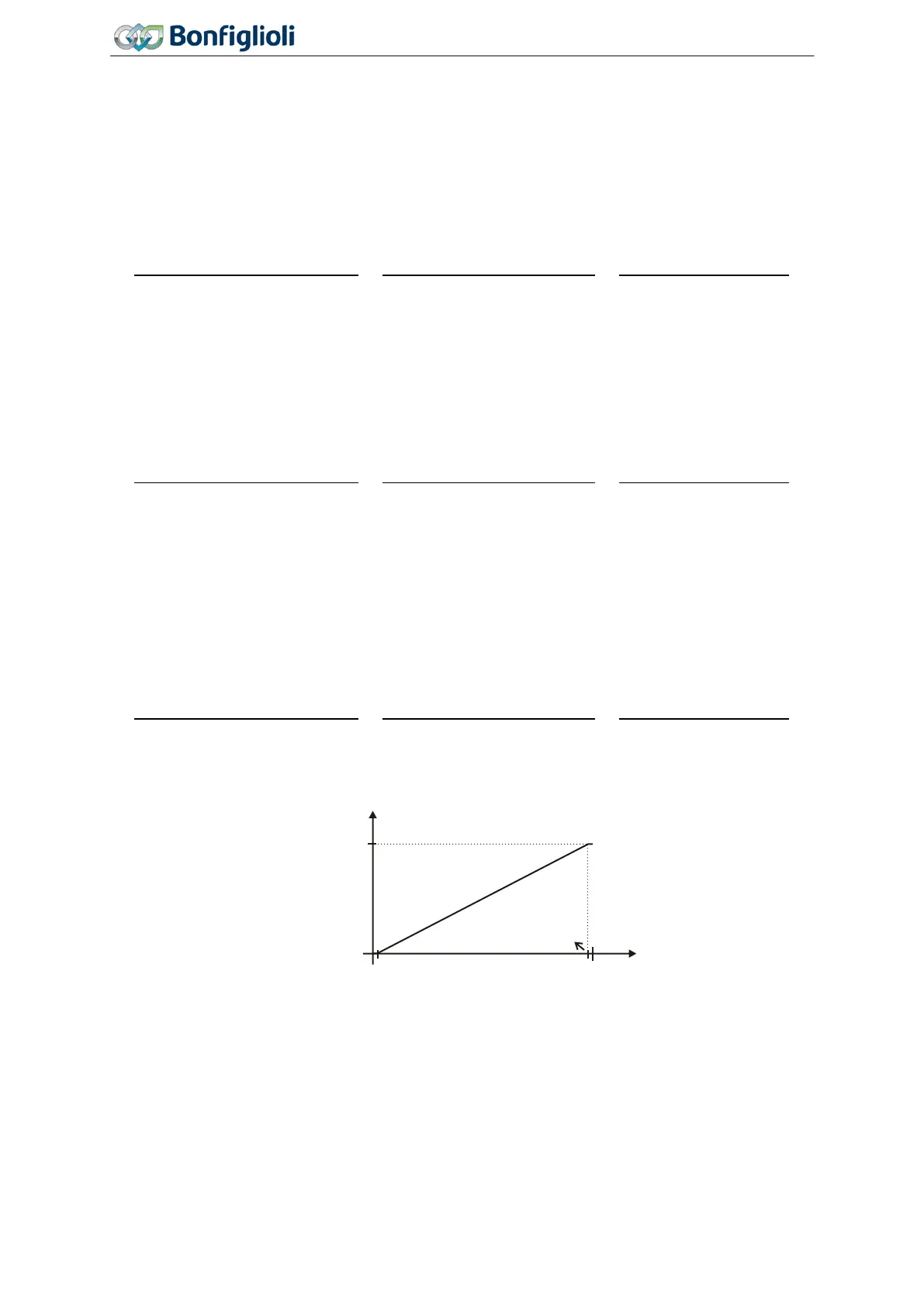
Operation Mode MFI1 452 is set to "1 - Voltage 0…10 V". The coordinates of the points
relate, as a percentage, to the analog signal with 9.8 V and parameter
Maximum Frequency 419 or
parameter
Maximum Reference Percentage 519. The zero-crossing of the frequency or the percent-
age value lies at 0.2 V. The deviations from 10 V and 0 V allow the operation even with voltage sup-
plies that have small deviations from the nominal values.
Incliniation:
9.8 0.2
=
9.6
419
=
9.6
. 519
Current 0…20 mA
Current 0…20 mA
Parameter
Operation Mode MFI1 452 must be set to "2 - Current 0…20 mA". The coordinates of the
points relate, as a percentage, to the analog signal with 19.6 mA and parameter
Maximum Frequen-
cy
419 or parameter Maximum Reference Percentage 519. The zero-crossing of the frequency or the
percentage value lies at 0.4 mA. The deviations from 20 mA and 0 mA allow the operation even with
voltage supplies that have small deviations from the nominal values.
Incliniation:
19.6 0.4
=
19.2
419
=
19.2
. 519
Current 4…20 mA
Parameter
Operation Mode MFI1 452 must be set to "5 - Current 4…20 mA". The coordinates of the
points relate, as a percentage, to the analog signal with 19.6 mA and parameter
Maximum Frequency
419 or parameter Maximum Reference Percentage 519. The zero-crossing of the frequency or the
percentage value lies at 4.4 mA. The deviations from 20 mA and 4 mA allow the operation even with
voltage supplies that have small deviations from the nominal values.
Incliniation:
19.6 4.4
=
15.2
419
=
15.2
. 519
0 V
(0 mA)
(20 mA)
50 Hz
+10 V
(+20 mA)
(+20 mA)
9.8 V
0.2 V
f [Hz]
U [V]
P562=1
(P562=2)
(P562=5)
176
Operating Instructions
Agile
06/2013 Control inputs and outputs

 Loading...


