94 100-412-234 REV. 06
5.10 Testing the Installation
1. Turn on the air supply connections including the pneumatic dump valve and verify that the air
pressure indicator light in the actuator is lit
2. Ensure there are no leaks in the air supply connections
3. Turn on the power supply. The power supply will begin its normal self-check
4. If the power supply displays an alarm message other than Recalibrate Actuator, find the alarm
message definition, cause and correction in
Chapter 7: Actuator Operation. If the power supply
displays the alarm message Recalibrate Actuator, go on to the next step
5. Perform an actuator calibration by touching the Main Menu button, and then press the Calibration
button. Verify that there is a minimum clearance from horn face to workpiece greater than 0.70"
6. Touch Cal Actuator
7. In the screen that follows, touch w/Start Switches
8. Press the Start switches to complete the calibration
9. Press the Test button
10.If the power supply displays an alarm message at this point, find the alarm message definition in
Appendix B: Alarms. If there are no alarm messages displayed, go on to the next step
11.Fit a test part onto the fixture
12.Touch Horn Down on the Main Menu and press the palm buttons. The horn will descend to the
fixture on the base of the actuator. This verifies specifically that the pneumatic system is working
13.Press the Retract button. The horn will retract. The system should now be functional and can be
set up for your application
In summary, if the power supply does not display an alarm message and descends and
retracts correctly, your ultrasonic welder is ready for operation
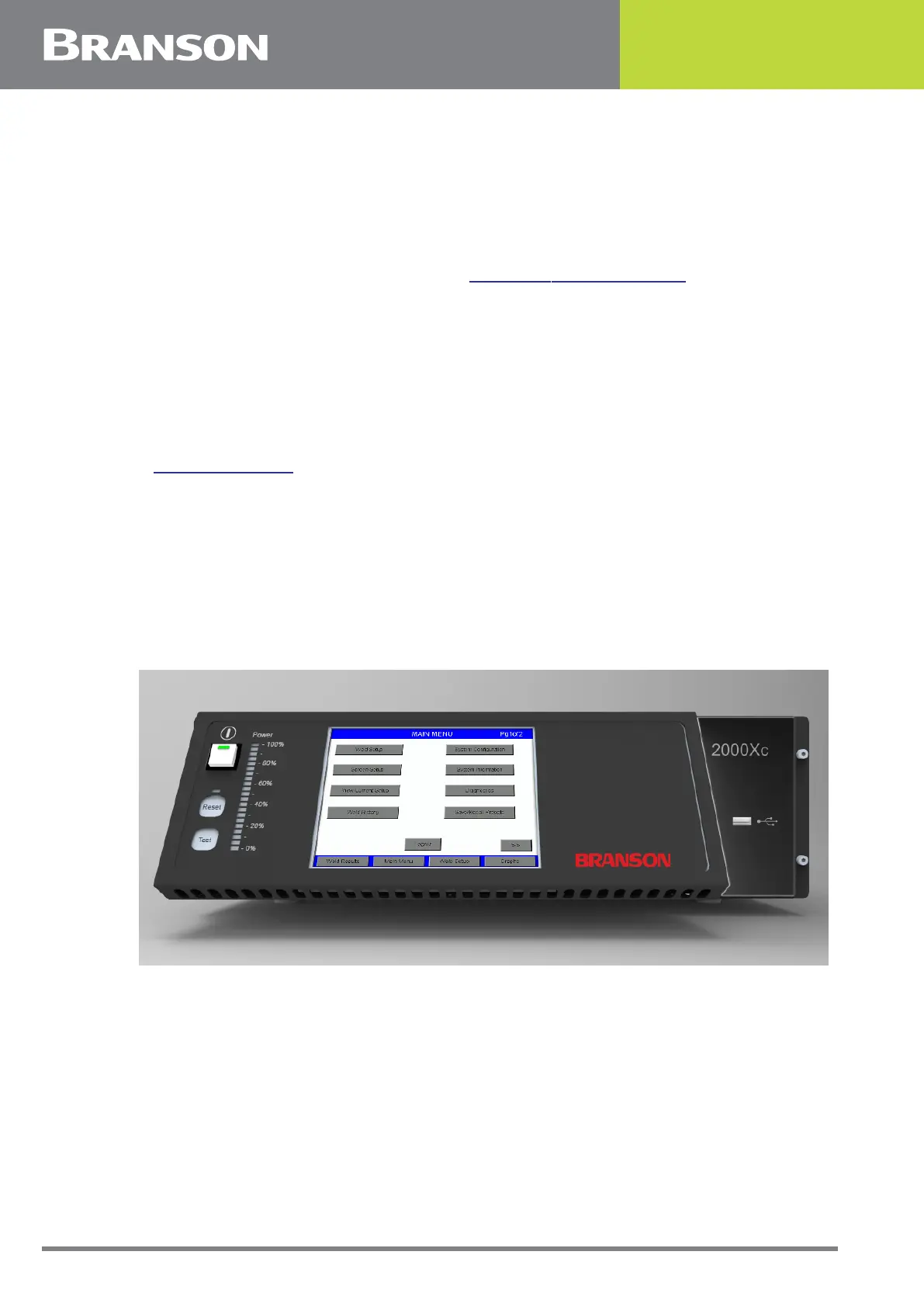
Figure 5.20 Front Panel Display