80 100-412-234 REV. 06
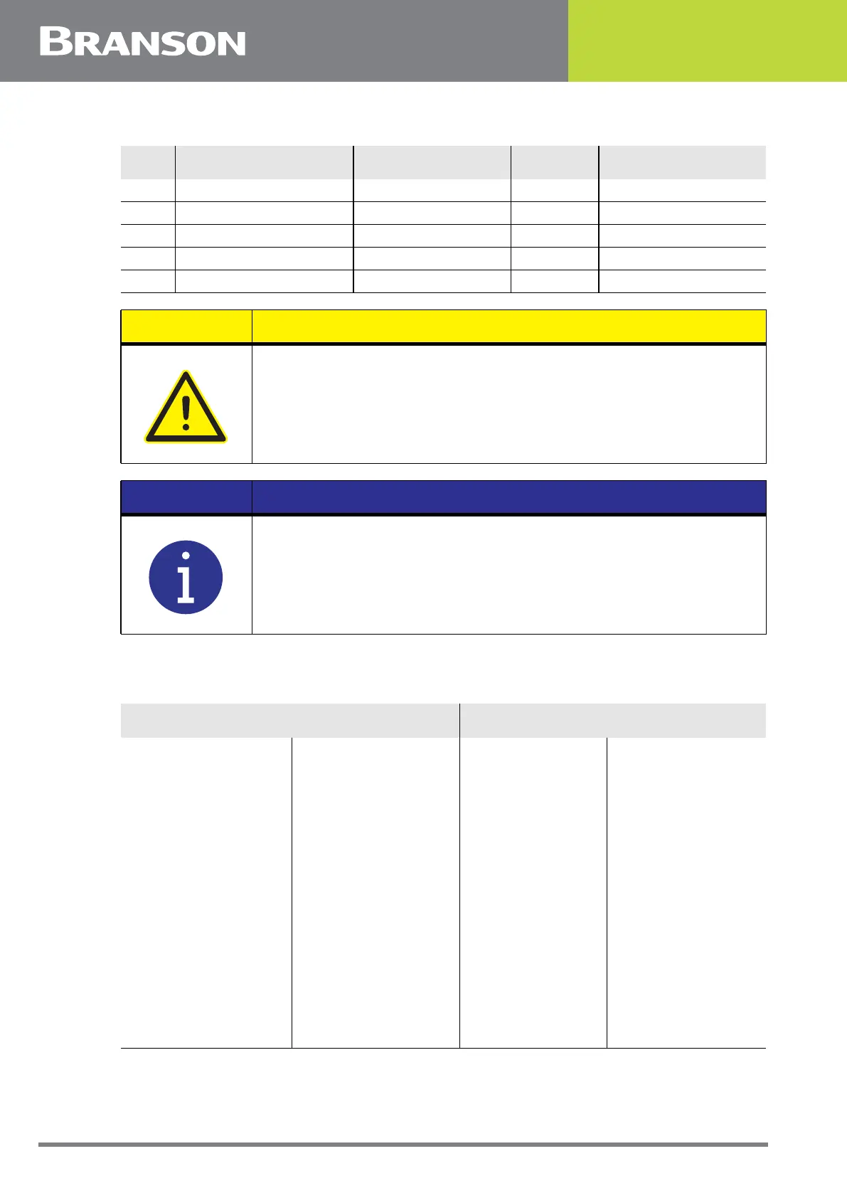
40 MEMORY_STORE Open Collector Output Red/White/Blue
41 Analog GND Green/Orange/Red
42 +24V Orange/Red/Blue
43 READY_RELAY_1 Relay Contact Output Blue/Orange/Red
44 WELD_ON_RELAY Relay Contact Output Black/Orange/Red
CAUTION
Ensure all unused wires are properly isolated. failure to do so may
result in power supply or system failure.
NOTICE
When syncing multiple systems, refer to the Branson Automation
Guide (EDP 100-214-273) for additional information about selection
and use of Input and Output features listed in the following Table.
Table 5.6 Inputs/Outputs
Input Output
J3_1_INPUT
J3_17_INPUT
J3_19_INPUT
J3_31_INPUT
J3_32_INPUT
J3_33_INPUT
Disabled
Select Preset
Ext U/S Delay
Display Lock
Ext Signal
Sonics Disable
Memory Reset
Ext Tooling
Sync In
Part Present
Confirm Reject
J3_8_OUTPUT
J3_22_OUTPUT
J3_36_OUTPUT
Disabled
Confirm Preset
Ext Beeper
Cycle OK
No Cycle Alarm
Overload alarm
Modified Alarm
Note
Missing Part
Ext Tooling
Sync Out
Part-ID Ready
Table 5.5 User I/O Cable Pin Assignments
Pin Signal Name Signal Type Directio Colors