112 100-412-234 REV. 06
6.6 Testing the Welding System
After the power supply is installed, you can confirm that the ultrasonic welding system is
operational by following this test procedure using a sample part. This assumes that the
installation has been set-up and tested per Chapter 5: Installation and Setup of this
manual.
To test the Welding System after installation, do the following:
*The default screen is Main Menu. The Weld Results screen can also be chosen as the startup screen on the Sys-
tem Configuration Menu.
Table 6.4 Testing the Welding System
Step Action
1
On the actuator column, adjust the stroke length to 1/4 inch or more,
depending on the part you will use for the test run. Position the system to
allow for a minimum stroke length of 1/4 inch or more. Lock column after
adjusting.
2 Position the part in the tooling.
3
Verify that factory air supply has been connected to the actuator and turned
on. (If using optional pneumatic dump valve, ensure it is turned on.)
4
On the power supply front panel, press the power switch. The indicator light
on the front of the actuator becomes illuminated.
5
The power supply will go through its normal turn on sequence. At the end of
this sequence the Main Menu screen is displayed*.
If the power supply displays an alarm message, find the alarm message
definition, cause, and correction in Chapter 8: Maintenance of this manual. If
the alarm message is Recalibrate Actuator, return to Chapter 5: Installation
and Setup, and re-run the procedure in 5.10 Testing the Installation.
6
On the power supply touchscreen, press the Weld Setup button. Press the
Trigger Force button. Set Trigger Force to 10 lbs.
7 On the power supply touchscreen, press the Weld Results key.
8 Activate both Start Switches simultaneously.
9
When the weld cycle is complete, and if the cycle has completed successfully,
the cycle counter increments to show a completed cycle.
If the Reset LED on the power supply front panel flashes and the second line
displays an alarm message, the test did not complete successfully. See 8.6
Troubleshooting, for information on alarm conditions and how to correct
them.
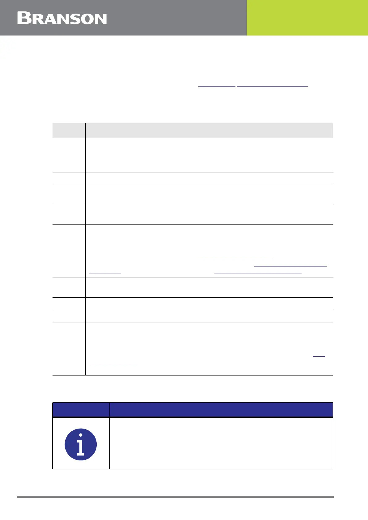
NOTICE
If you power up and the actuator is not home, you will get two
alarms. One is the Recal Actuator Alarm. Restore air to the system
and power up again and a recal will not be needed.