72 100-412-234 REV. 06
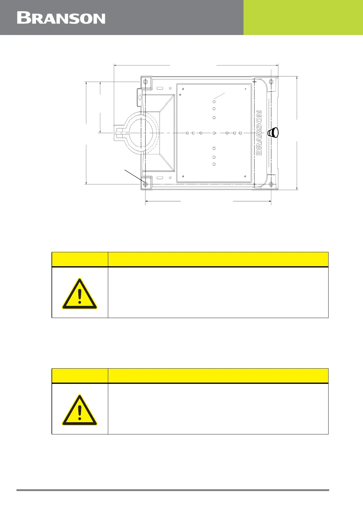
Figure 5.7 Base Mounting Centers
5.5.2 Actuator (Alone)
The actuator (alone) is intended for installation on your custom-made mounting support.
It is located in place with a mounting pin and secured using three metric bolts.
1. Lift the actuator from the box. Carefully lay the assembly on its right side (NOT on the side with
the linear encoder)
2. Use of a guide pin is suggested. It is not provided with the actuator. If you require a guide pin,
use a solid metal dowel pin, 12mm diameter, which must not extend into the actuator more than
0.40 inch (10mm) from your support
21.31 in / 541 mm
Mounting Holes
accept 3/8 inch
or metric M10
cap screws
14.75 in /
375 mm
7.37 in /
187 mm
16.5 in /
419 mm
M10
M
28.0 in / 711 mm
CAUTION
In a custom installation, the actuator must be mounted on an I-beam
or other rigid structure. The mounting surface must be flat within
0.004 in (0.1mm) Total Indicator Reading, in a tolerance zone of 16 x
3.5 in (410 x 90 mm).
CAUTION
The actuator support bolts for the 2000Xc-series actuators are
metric, M10 x 1.5 thread pitch, 25mm long. The support pin and
mounting bolts must not extend more than 0.40 in (10 mm) into the
actuator, otherwise, binding or damage to the carriage may occur.