210 100-412-234 REV. 06
8.8.1 Power Supply Cover
The cover is held in place with seven screws, three on each side of the case and one on
the rear. Lift the rear of the cover up to remove it. The cover must be in place when the
system is operating due to fan-forced ventilation design.
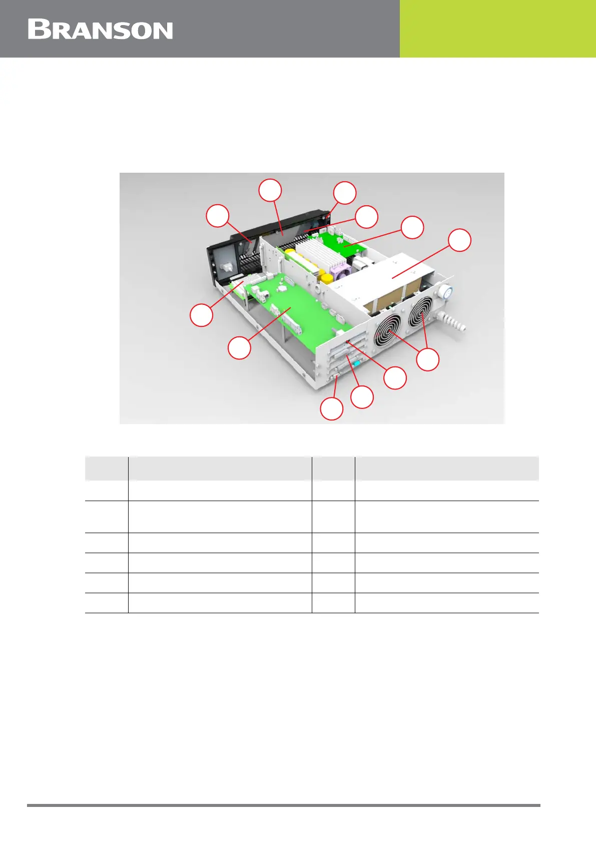
Figure 8.3 Component Location of 2000Xc Modules
Table 8.7 2000Xc Modules
Item Name Item Name
1 VGA Inverter Board 2 VGA Display with VGA PC Board
3
Membrane Keypad ground ribbon
attach point
4 VGA Touchscreen Controller
5 Ultrasonic Power Supply Module 6 DC Power Supply Module
7 Single Computer Board 8 System Controller Board
9 External VGA Connection 10 USB
11 RJ-45 Ethernet 12 Cooling Fans
8
7
9
10
11
12
1
2
3
4
5
6