76 100-412-234 REV. 06
5.5.7 Start Switch Connection
A Branson actuator requires 2 start switches and emergency stop connection. Stands on a
base include this connection (factory installed and connected from the base) while the
stand on a hub and actuator (alone) applications require the user make their own start
switch/E-stop connections, as follows:
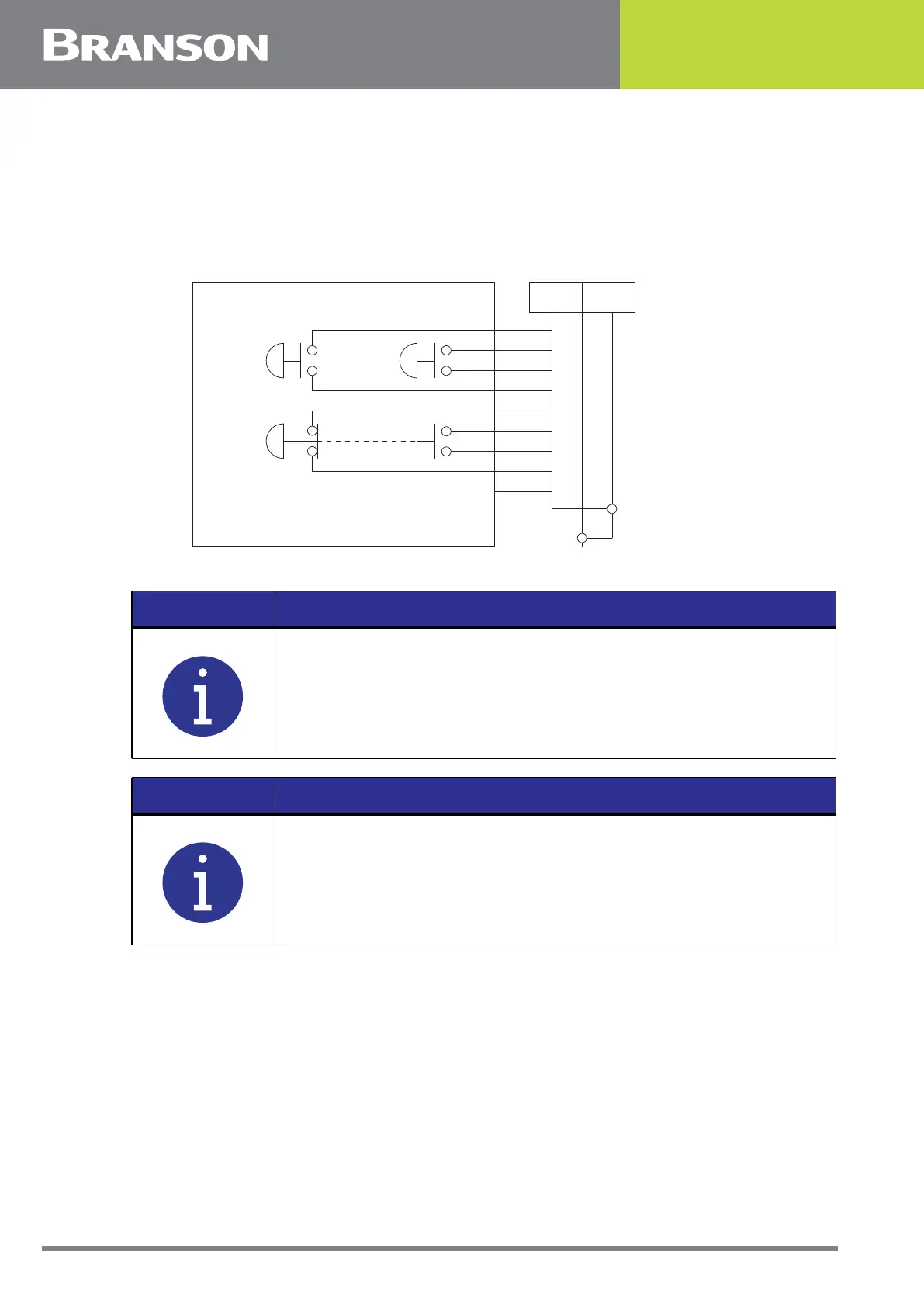
Figure 5.10 Start Switch Connection Codes (CE Actuator)
EMER STOP is an emergency stop switch, with both normally closed and normally open contacts.
BASE/START is the DB-9 female connection on the back of the actuator. Your cable
requires a male DB-9 (D-shell) connector.
PB1 and PB2 are two normally open start-switches which must be operated
simultaneously to start the welding cycle. These must be closed within 200 milliseconds of
each other, or error message: “Start Sw Time” will display. This doesn’t require a reset,
NOTICE
Solid state devices may be used in lieu of mechanical start switches
providing their leakage current does not exceed 0.1mA.
NOTICE
Start Switches PB1 and PB2 must be closed within 200 milliseconds
of each other, and remain closed until the PB Release signal is active,
to effect a start condition.
PB2 PB1
PALM BUTTON START
EMER
STOP
1
P69 P69-A Color Codes
2
6
7
9
8
3
4
5
1 PB2RTN
PB1RTN
24VSRC
24VSRC
ESTOPSRC
ESTOPSRC
ESTOPRTN
ESTOPRTN
N/C
Black
White
Blue
Orange
Purple
Yellow
Red
Green
Brown
2
6
7
9
8
3
4
5