128 100-412-234 REV. 06
6.9.33 Setting Limits
From within any weld mode, you can set the main parameter (indicated by the name of
the weld mode) and Hold Time and several other parameters. The other parameters you
can set include Suspect Limits and Reject Limits. You can reduce the amount of scrap from
unacceptable parts by identifying those parts that are slightly out of range using Suspect
and/or Reject Limits. Upon manual inspection, you might find that these parts are
acceptable. You can set the Suspect and Reject Limits on the power supply to identify (by
counter, output, or alarm) all parts that fall into limit categories.
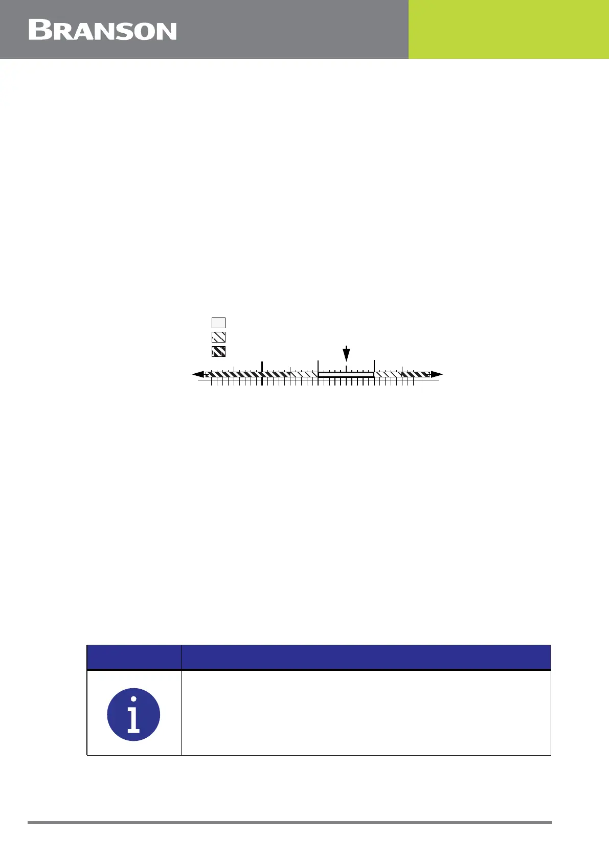
For example, consider a weld cycle in Time Weld Mode, where you have set the time to
0.280 second. You have determined (by laboratory testing, trial and error, or some other
means) that you get an acceptable weld when 100 to 110 Joules of energy have been
transmitted to the part. These are the limits that you should then set on the power supply
as Suspect Limits. You have also determined that the part is a “reject” if it received fewer
than 95 Joules or more than 115 Joules. This is illustrated by the following graph:
You can set Suspect and Reject Limits for meaningful parameters in each weld mode.
Figure 6.21 Setting Limits
6.9.34 Reject Limits
You can select whether to use Reject Limits to indicate that a part does not have a good
weld. You can set limits of minimum and maximum time allowed for:
• weld time
• energy levels
• peak power levels
• collapse distance
• absolute distance
• trigger distance
• weld force
• frequency
• downspeed
If you set Reset Required to Yes, when an alarm is generated, you will need to press the
Reset key prior to welding another part.
80 90 100 110
.
Energy in Joules
Part is “Reject” (<95 or >115 J)
Part is a “Suspect” (95-100 J or 110-115 J)
11595
Part is Good (100-110 J)
NOTICE
Reject limits put out a signal to pins 20 and 5 of J3 respectively. The
44 pin I/O cable J957 connects to J3.