218 100-412-234 REV. 06
8.8.10 Line Board
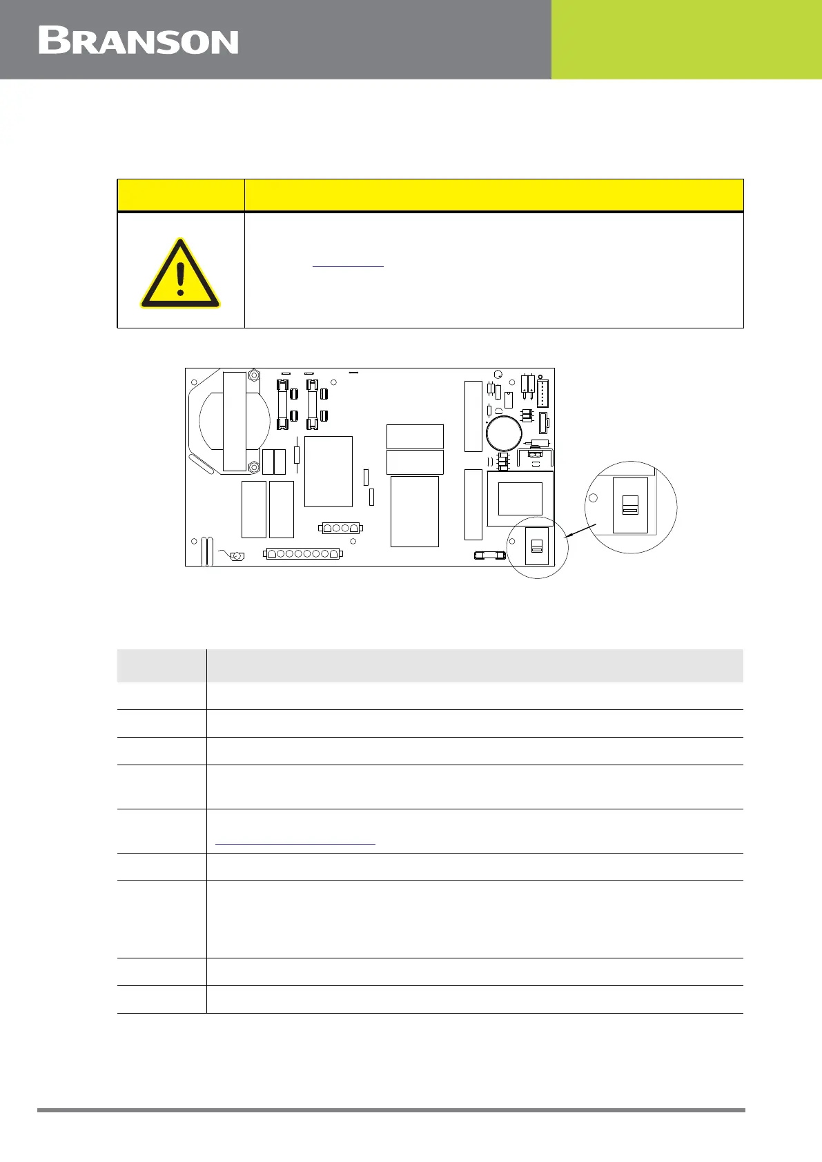
Figure 8.6 Lineboard EDP 100-242-1199R (100-242-1230R for 4kW units)
To remove the Line Board, take the following steps:
CAUTION
Refer to Figure 8.6 below to verify the voltage selector switch is
configured properly for your intended operating voltage.
Table 8.13 Removing the Line Board
Step Action
1 Turn off the power supply.
2 Unplug the main power.
3 Allow at least two minutes for capacitor discharge.
4
Using a #2 Phillips screwdriver, remove 7 screws from the 2000Xc Power
Supply cover (3 on each side, 1 on the rear). Remove the cover.
5
Rotate the DC power supply up to allow you access to the Line Board. See
8.8.6 DC Power Supply.
6 Disconnect J26, J27, J28, and J29.
7
For 120 V systems, disconnect line labeled E1 and neutral labeled E4 or N.
For 220 V systems, disconnect lines labeled E1 and E2.
Note that the brown lead is the hot lead.
8 Remove 5 M3 screws (Phillips) and 1 ground screw (common head).
9 Lift out the line board.
C9
F4
J29
U2
R2
R8
R7
R4
C10
J27
C15
D5
D1
Q1
230V
SW1
D6
U1
D3
D4
D2
R3
R6
LED1
C16
T1
C14
R5
F3
FUSE
3A 250V
E2
E1
E4
E3
F1
F2
L1
C8
C7
R9
K1
FUSE
20A 250V
MOV3
SP1
MOV2
C5
C6
J26
E5
J28
LINE BOARD
100-242-1199R
ZR1
ZR2
C3
C11
K2
MOV1
230V
SW1