82 100-412-234 REV. 06
5.5.10 User I/O DIP Switch (SW1)
DIP switch SW1, for the user I/O is located next to the J3 on the back of the 2000Xc
Power Supply, as shown in Figure 4.2 Rear View of 2000Xc Power Supply. The settings of
these switches affect the user I/O signals. Factory default setting is for all dip switches is
set to ON (closed: switch position closest to number designation).
• If the DIP switch is set to the ON (closed) position, the corresponding Output pin will be
configured as the current source, 25mA max
• If the DIP switch is set to the OFF (open) position, the corresponding Output pin will be
configured as an “open collector”, 24VDC, 25 mA max. current sink
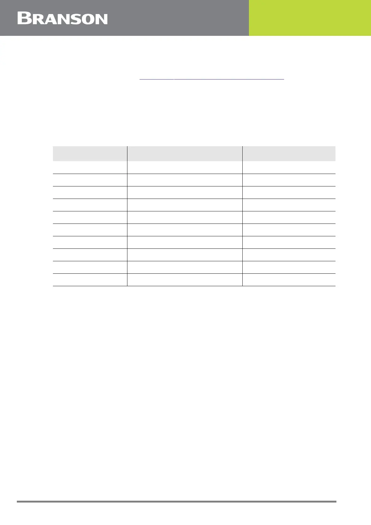
Table 5.7 User I/O DIP Switch Functions
Switch Position Signal Description Output Signal
1 REJECT_SIG REJECT
2 SUSPECT_SIG SUSPECT
3 PB_RELEASE_SIG PB_RELEASE
4 G_ALARM_SIG G_ALARM
5 READY_SIG READY
6 WELD_ON_SIG WELD_ON
7 ACTUATOR_CLEAR_SIG ACT_CLEAR
8 J3_22_OUT_SIG J3_22_OUTPUT
9 J3_36_OUT_SIG J3_36_OUTPUT
10 J3_8_OUT_SIG J3_8_OUTPUT