Field Service Ver. 1.0 Aug. 2005 4. Other
15
SD-502Maintenance
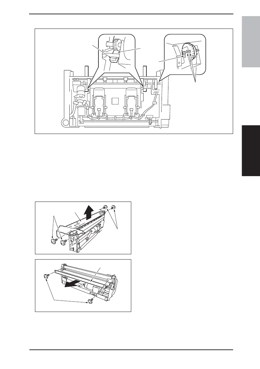
Precaution for In & Out Guide Drive Motor Reinstallation
1. Press the two In & Out Guides [1] in and check that they touch the stopper [2] simulta-
neously.
2. Check that pins [4] can be inserted through the positioning holes [3] (3 holes) of the In
& Out Guide Sensor Assy.
3. Use two screws to secure the In & Out Guide Drive Motor.
4.3.8 Crease Roller
1. Remove the Crease Unit.
☞ 8
2. Remove four screws [1], and remove
the Upper Plate [2].
3. Remove two screws [3], and remove
the guide plate [4].
4511F2C533DA
[1]
[2]
[3]
[4]
4511F2C534DA
[1]
[2]
[1]
4511F2C535DA
[3]
[4]