Chapter 4 Operation4.7 Standard Interface
144
(4) Example of Use
Assuming the external DIO is assigned to Input Port No. 16 to 31 and Output Port No. 316 to 331
(Initial value: set value in normal delivery), shown below is an example for setting to assign the
external DIO to the system IO as shown below.
Shown below is an example for setting to display the LED lamps (RDY, ALM, EMG and HPS) on the
panel window as they currently do.
Input port No.16 = Program Start Signal (ON Edge) (BCD-specified)
Input port No.17 = Servo ON Signal
Input port No.18 to 23 = Program number specified for program start No.
Input port No.24 = Error Reset (ON Edge)
Input port No.25 = All Effective Axes Homing (ON Edge)
Output port No.316 = Output error of operation-cancellation level or higher (ON)
Output port No.317 = READY output (PIO trigger program can be run)
Output port No.318 = Emergency-stop output (ON)
Output port No.319 = Output during automatic operation
Output port No.320 = Output when all effective linear drive axis home-return operation is
complete (coordinate is established)
Output port No.321 to 323 = Output while the 1 to 3 axes servo is on
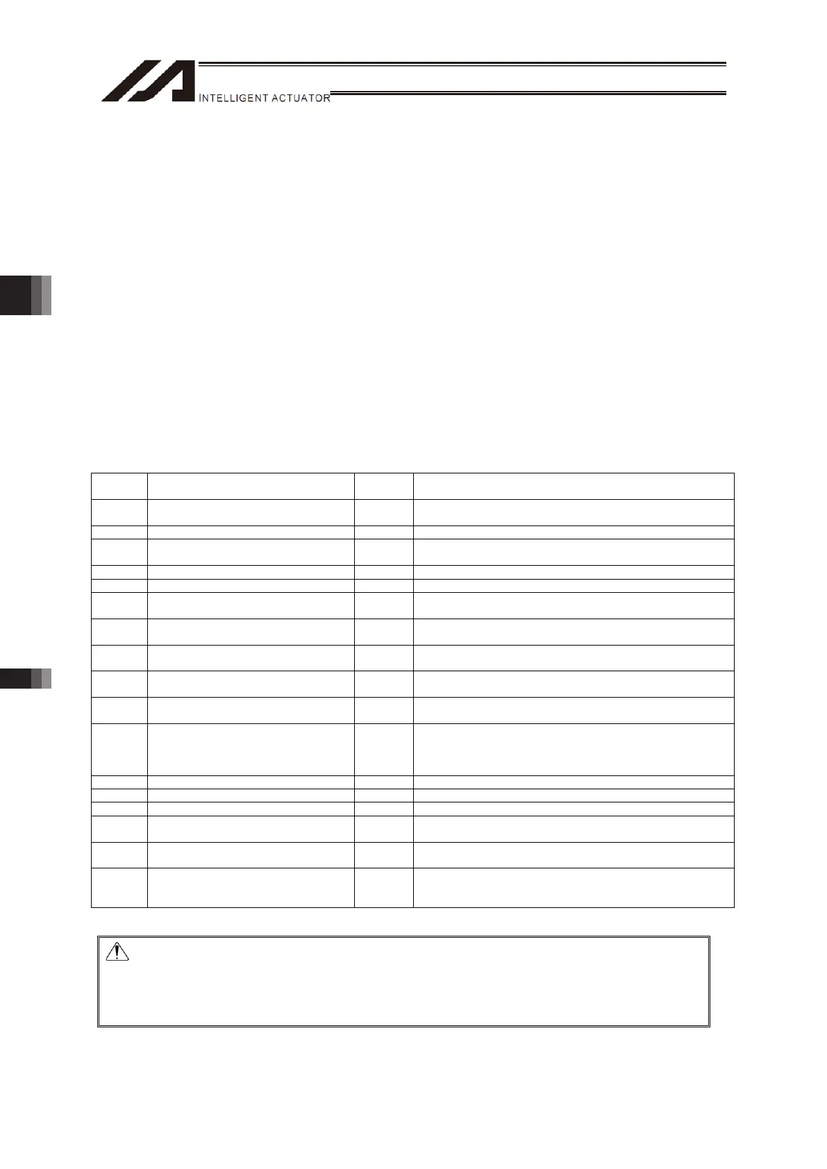
I/O parameter setting value
No. Parameters Example
Setting
Value
Remarks
30 Input function select 000 1
1 (Default value) = Program Start Signal (ON Edge)
(BCD-specified)
32 Input function select 002 1 1 = Servo ON
37
to 42
Input function select 007 to 012 1
1 (Default value) = Program number specified for program
start No.
43 Input function select 013 2 2 = Error reset (ON Edge)
45 Input function select 015 1 1 = All effective axes homing (ON Edge)
283
Input function select 000
Physical Input Port Number
16 Input port No. = 16
285
Input function select 002
Physical Input Port Number
17 Input port No. = 17
290
to 295
Input function select 007
Physical Input Port Number
18
to 23
Input port No. = 18 to 23
296
Input function select 013
Physical Input Port Number
24 Input port No. = 24
298
Input function select 015
Physical Input Port Number
25 Input port No. = 25
315
to 330
Output function select 300 (Area 2)
Physical Input Port Number
to Output function select 307 (Area 2)
Physical Input Port Number
316
to 323
Output port No. = 316 to 323
331 Output function select 300 (Area 2) 1 1 = Output error of operation-cancellation level or higher (ON)
332 Output function select 301 (Area 2) 1 1 = READY output (PIO trigger program can be run)
333 Output function select 302 (Area 2) 1 1 = Emergency-stop output (ON)
334 Output function select 303 (Area 2) 2
2 = Output during automatic operation
(Other parameter No. 12)
335 Output function select 304 (Area 2) 2
2 = Output when all effective linear drive axis home-return
operation is complete (coordinate is established)
336
to
338
Output function select 305 (Area 2)
to Output function select 307 (Area 2)
2
2 = Output while the 1 to 3 axes servo is ON
(System monitoring task output)
Caution: • When Input Function Select 000 (Start) is assigned to another input port, “Star
Switch” on the front panel would not work as “Program Start Signal”.
• When Input Function Select 007 to 013 (Digi-Switch) are assigned to other input
ports, “Program Switch” on the front panel would not work as “Program Start
Indication Program Number”.

 Loading...