Chapter 5 List of Parameters 5.3 Axis-Specic Parameters
183
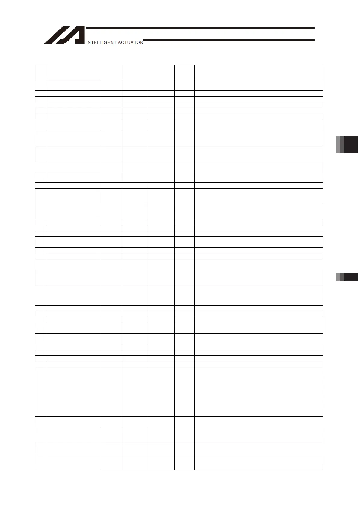
Axis-Specific Parameters
No. Parameter name
Default
value
(Reference)
Input range Unit Remarks
47 Screw lead Common 16000
-1 ~
99999999
0.001mm Valid only for linear movement axes.
48 (For extension) Common 0
49 (For extension) Common 0
50 Gear ratio numerator Common 15 1 ~ 99999999
51 Gear ratio denominator Common 10 1 ~ 99999999
52 (For extension) Common 0
53
Setting bit pattern 1 of
each axis
Common 0
0H ~
FFFFFFFFH
54
Travel distance for push
stop detection at home
return
Common 20 1 ~ 99999 0.001mm Used to confirm pusing action at the time of home return.
55
Travel distance for push
stop detection at
positioning
Common 30 1 ~ 99999 0.001mm Used to confirm pusing action according to the PUSH command.
56
Push-abort deviation
ratio at home return
Common 5000 1 ~ 99999
Deviation is compared against “Steady-state deviation of push
speed + Push-speed pulse speed × Abort deviation ratio.
57
Push-abort deviation
ratio at positioning
Common 5000 1 ~ 99999
Deviation is compared against “Steady-state deviation of push
speed + Push-speed pulse speed × Abort deviation ratio.
58 Positioning band Common 100 1 ~ 9999 0.001mm
Pulse
Motor
Type
218 1 ~ 9999
Deviation is compared against “Steady-state deviation of maximum
operating speed of each axis + Pulse speed of maximum operating
speed of each axis × Allowable deviation error ratio.”
59
Allowable deviation error
ratio
(Maximum speed pulse
ratio)
AC Servo
Motor
Type
27 1 ~ 9999
Deviation is compared against “Steady-state deviation of maximum
operating speed of each axis + Pulse speed of maximum operating
speed of each axis × Allowable deviation error ratio.”
60 Position gain Common 50 1 ~ 9999 /s
61 System reservation Common 0 0 ~ 500 %
62 System reservation Common 77 0 ~ 1000
63
Stop special output
range
Common 0 0 ~ 9999 pulse Invalid if “0” is set.
64 Stop special output value Common 0 0 ~ 999 DRVVR
65 System reservation Common 0 0 ~ 8
66
Mode selection for
rotational movement axis
Common 0 0 ~ 5
0: Normal
1: Index mode
67
Short-cut control
selection for rotational
movement axis
Common 0 0 ~ 5
0: Do not select
1: Select (Valid only in the index mode and when an incremental
encoder is used)
68
Mode selection for linear
movement axis
Common 0 0 ~ 5
0: Normal
1: Infinite-stroke mode
(Note: Positioning boundary applies. This setting can be
specified only when an incremental encoder is used.)
69 (For extension) Common 0 ~
70 System reservation Common 32767 0 ~ 32767 DRVVR (Change prohibited)
71 System reservation Common 32767 0 ~ 32767 DRVVR (Change prohibited)
72 System reservation Common 1 -999 ~ 999 DRVVR
(Change prohibited) To maintain symmetry of the positive and
negative sides.
73 System reservation Common 0 -999 ~ 999 DRVVR
(Change prohibited) To maintain symmetry of the positive and
negative sides.
74 System reservation Common 32436 0 ~ 32767 DRVVR (Change prohibited)
75 System reservation Common -32435 0 ~ -32767 DRVVR (Change prohibited)
76 System reservation Common 1 0 ~ 1 (Change prohibited)
77 System reservation Common 3 0 ~ 99999 pulse
78
Maximum takeoff
command amount
Common 0 -3000 ~ 3000 0.001mm
Maximum lift command amount before brake unlock (Input with
sign) (Suppression of momentary drop upon servo ON when a
heavy object is placed)
* Important: Input using the same sign as the rising coordinate
direction. (0.100 mm to 0.500 mm in absolute value
as a guideline)
* The servo-ON check time (Axis-Specific Parameter No. 30) must
also be extended (Approx. 1000 to 1500 msec) to provide a
sufficient time for rise-direction torque to follow.
(Valid only when installation of brake is specified.)
79
Actual takeoff check
distance
Common 5 0 ~ 3000 0.001mm Absolute value input
80
Maximum forced-feed
range
Common 0 0 ~ 9999 0.001mm
For reduction of settling time.
(Invalid range if “0” is set)
(Approx. 1.000 mm as a guideline)
81
Minimum forced-feed
range
Common 200 0 ~ 9999 0.001mm
82
Medium forced-feed
range
Common 600 0 ~ 9999 0.001mm
83 System reservation Common 0 0 ~ 5

 Loading...