27
About Coordinate System
The coordinate system of the coordinate system definition unit consists of four coordinates (X-axis,
Y-axis, Z-axis and R-axis) at the maximum.
The coordinate value on the home of each axis is 0mm of the position data.
The position from the home is the position data for each axis.
For TTA, there are three types of coordinate systems in addition to the coordinate system defined
for each axis (each axis system), which are base coordinate system, work coordinate system and
tool coordinate system.
(Note) To use coordinate systems other than the each axis system, it is necessary to activate the
features for work and tool coordinate systems. For details, refer to “Work and Tool
Coordinate Systems for Liner Axis” in “Chapter 7 Appendix”.
Each Axis System
Base Coordinate System
Coordinate System
Work Coordinate System
Tool Coordinate System
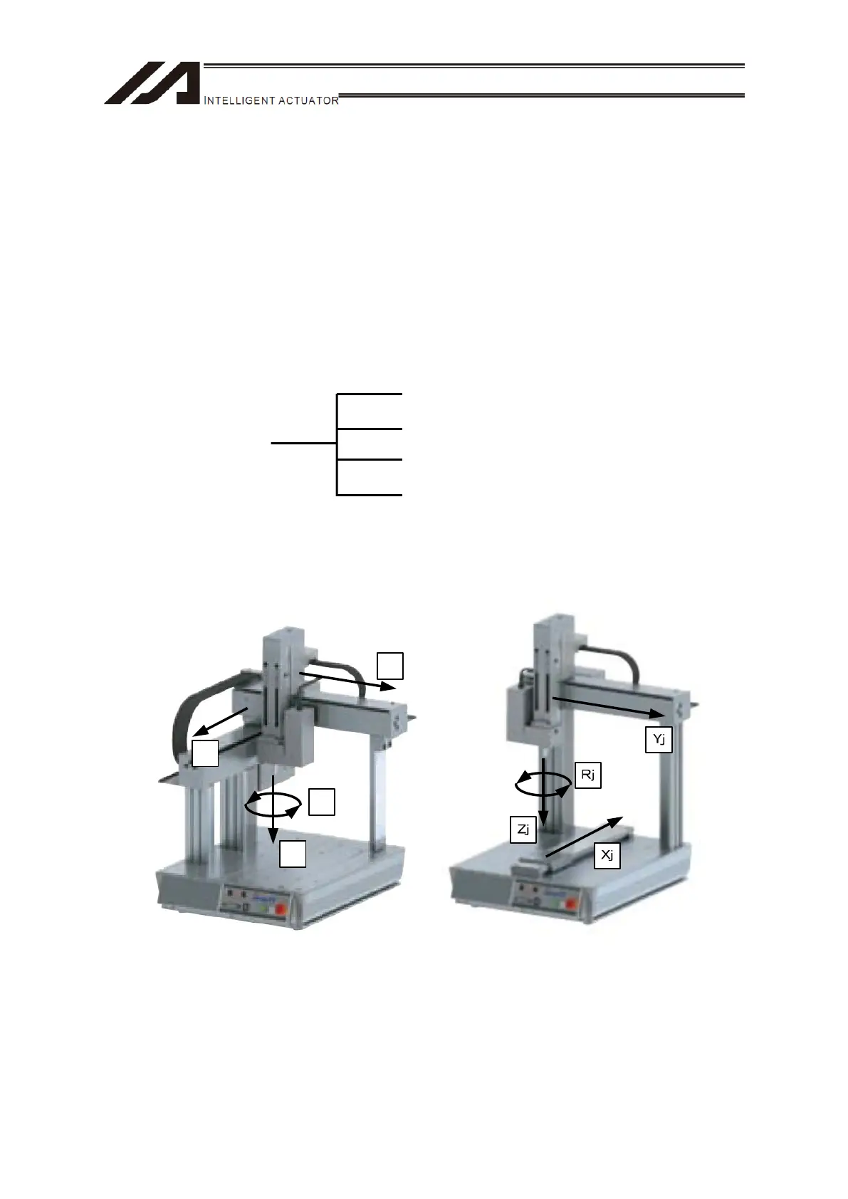
1. Each Axis System
Each axis system is the coordinate system specific for each linear axis.
In below, shows each axis system in four-axis type TTA for example.
Xj
Yj
Rj
Zj
Figure : Example for Each Axis System in Four-Axis Type TTA (XYZ Home Standard
Specification) (Left:TTA-C4 / Right:TTA-A4)

 Loading...